Continue to Site

Welcome to EDAboard.com

Welcome to our site! EDAboard.com is an international Electronics Discussion Forum focused on EDA software, circuits, schematics, books, theory, papers, asic, pld, 8051, DSP, Network, RF, Analog Design, PCB, Service Manuals... and a whole lot more! To participate you need to register. Registration is free. Click here to register now.

[SOLVED] Suitable topology for 150Ah battery charging

Status
Not open for further replies.

mrinalmani

Advanced Member level 1
Joined
Oct 7, 2011
Messages
463
Helped
60
Reputation
121
Reaction score
58
Trophy points
1,318
Location
Delhi, India
Activity points
5,285
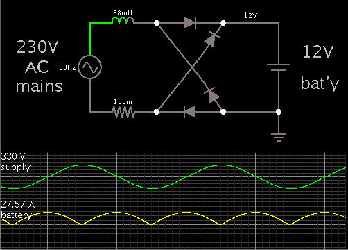
I am required to make a battery charging circuit for a high frequency sine wave inverter, rated 12V/230V, 850VA
Target battery size is 100AH to 180AH. And thus charging current capability of upto 20A is desired.
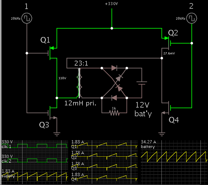
There is a HF transformer on board, how can this be utilized to charge the battery, without using an additional H-Bridge. I am having difficulties in getting the X-mer rest.

I have another idea of using a buck converter, switched with a low voltage drop IGBT (FGD4536
360 V PDP Trench IGBT). This IGBT is cheap and has a voltage drop of approx 1.3V @ 25A. Although I am not very reluctant about using the buck converter for step-down ratio as high as 1:20 at a current level of 20A. But there doesn't seem to another way.

Please give suggestions
 

If your current draw from mains AC is unchanging...

then you can install an inductor to act as a 'choke'.

The simulation works (theoretically) with a 38 mH inductor, to allow a charging current of 20A average.


If you draw less current, then voltage will go up. This makes such a method hazardous. It exposes the battery to high voltage. (Presumably it is lead-acid type?)

Nevertheless a buck converter carries a similar risk, as you believe you may use.

An alternative is to use capacitive drop, by putting a 270 uF capacitor (or bank of capacitors) where the inductor is. It must be non-polarized. It needs to be robust to carry 28A peak. This method has its risks as well.

The safest method is to use a transformer, of course.
 

Thanks for the suggestion...
But the 38mH inductor with a peak capacity of 28A is nothing short of an atom bomb!
Is there a way of using the same HF transformer that is being used to by the inverter to step up DC from 12V to 350V? The x-mer is unused when the mains is available?
 

Here is a typical way you would use a transformer to step down 330 VDC at high frequency.

It shows how you would need to re-arrange your transformer.


The 330 VDC comes from mains AC, rectified and filtered.

Values are flexible. However the simulator showed that charging current was greatly affected by the step-down ratio.

And of course no charging was possible where the secondary voltage did not rise high enough. This makes the step-down ratio a crucial factor.

Therefore your transformer may or may not be suitable in this application.

- - - Updated - - -

Additionally, the mosfet gates need a certain range of driving voltage. My simulation does not show realistic gate voltage levels.
 

Thanks for the reply....
But this schematic uses another H-Bridge ( which literally costs as much a transformer!)
Is there a way of using only one switch. If an additional winding with small number of turns is required, it is all right, but an H-Bridge becomes far too expensive. (think of mass production)
 

You are asking about a 300 W DC power supply. Reviewing how this task is usually achieved in recent products would be my first step. You don't need to reinvent the wheel, and shouldn't try to invent a square one.
 
I have decided upon a "two switch forward converter".
Please point out if the decision is pragmatically incorrect....
 

I have decided upon a "two switch forward converter".
Please point out if the decision is pragmatically incorrect....

We are talking about a converter of approximately 250 watts. This should be perfectly feasible with either a single or two switch forward converter.
But you must perform the proper mathematical analysis to determine actual feasibility.

Read the following presentation:

https://www.onsemi.com/pub_link/Collateral/TND378-D.PDF
 
Last edited:
Status
Not open for further replies.

Part and Inventory Search

Welcome to EDABoard.com

Sponsor

Back
Top