ruwan2
Member level 5
Hi,
I run a simulation about equalization on Serdes link with Simulink. It is from a demo file. Although it is effective, I cannot make up the equalization parameters with the result.
It is about 2 G Bit Per Second Serdes. Below picture shows that the distorted signal (up) and equalized signal (down):

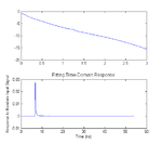
I get the distorted channel response picture as:

The above curve looks like match to the general FR4 board. Please note that it is a linear horizontal axis as the usual case for serdes channel.
The adopted equalizer is a lead-lag filter:
nominator: Tau1=25e-9
denominator: Tau2=10e-9
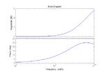
Its frequency response curve is:

I use bodeplot, whose default horizontal axis is in log. My question is that the high frequency compensation between 1G to 3G is rather small with the channel attenuation. This is far beyond of my expectation on equalizer high frequency boost. From 1G to 10G, the equalizer has at most 5.8 dB, comparing the -15 dB loss at 3G for the channel. The equalization looks like not enough, but the eye diagram above seems OK on the other hand.
Could you agree these figures? What is wrong with me?
Thanks,
I run a simulation about equalization on Serdes link with Simulink. It is from a demo file. Although it is effective, I cannot make up the equalization parameters with the result.
It is about 2 G Bit Per Second Serdes. Below picture shows that the distorted signal (up) and equalized signal (down):

I get the distorted channel response picture as:

The above curve looks like match to the general FR4 board. Please note that it is a linear horizontal axis as the usual case for serdes channel.
The adopted equalizer is a lead-lag filter:
nominator: Tau1=25e-9
denominator: Tau2=10e-9
Its frequency response curve is:

I use bodeplot, whose default horizontal axis is in log. My question is that the high frequency compensation between 1G to 3G is rather small with the channel attenuation. This is far beyond of my expectation on equalizer high frequency boost. From 1G to 10G, the equalizer has at most 5.8 dB, comparing the -15 dB loss at 3G for the channel. The equalization looks like not enough, but the eye diagram above seems OK on the other hand.
Could you agree these figures? What is wrong with me?
Thanks,
Last edited: