Continue to Site

Welcome to EDAboard.com

Welcome to our site! EDAboard.com is an international Electronics Discussion Forum focused on EDA software, circuits, schematics, books, theory, papers, asic, pld, 8051, DSP, Network, RF, Analog Design, PCB, Service Manuals... and a whole lot more! To participate you need to register. Registration is free. Click here to register now.

Antenna Link Budget in ADS Momentum

Status
Not open for further replies.

rlyc

Newbie level 3
Joined
Nov 23, 2013
Messages
3
Helped
0
Reputation
0
Reaction score
0
Trophy points
1
Activity points
23
Hi all,

I appreciate any help from you guys.

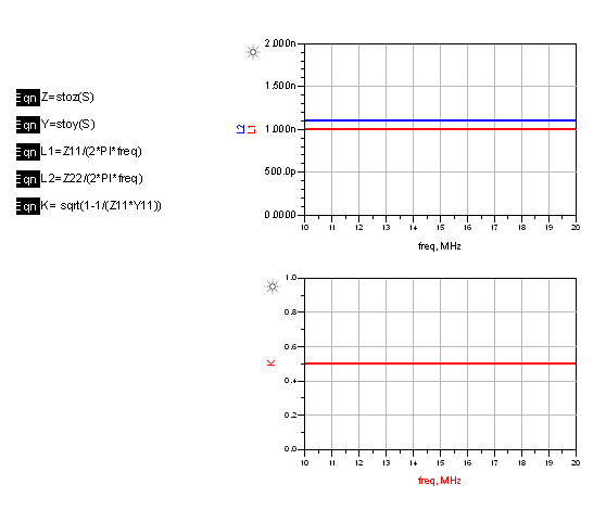
Below is a picture of a pair of inductors in ADS Momentum. They are match to their respective ports. The small coil sets on an dielectric substrate, and the bigger coil is hanging in free space. You can see it as a pair of NFC antennas.

The problem is that now I need to do power budget simulation on them to see how much power is lost at varies separation distances. How do I excite a port in Momentum, or does it have to be taken into schematics? Is schematic even able to consider magnetic inductance like this? what do I use to measure the current and voltage of the receiving inductor in schematics?

Thank you all so much

inductor_pair.png
 

These electrically small coils behave like coupled inductors and not like "real" antennas. Momentum is well suited to simulate this, and the setup is rather simple.

Port setup:
For each coil, you need two pins at the end of the conductors. Group these two pins into one port: in the port editor, use drag&drop to move one pin to the (-) terminal of the port. This will create a differential port from the two pins. Do the same for the other coil.

Now you have two ports, and can simulate S/Y/Z parameters. The coils behave like inductors, and we can calculate the inductance and coupling factor k from the simulation results.

Inductor parameter extraction:
In the ADS data display, create these two equations that calculate Y and Z parameters from the simulated S parameters:
Y=stoy(S)
Z=stoz(Z)
Now we can calculate the inductance of the two coils:
L1 = imag(Z11)/(2*PI*freq)
L2 = imag(Z22)/(2*PI*freq)
Calculate coupling factor k:
K= sqrt(1-1/(Z11*Y11))

That's it. You now have the relevant circuit parameters for your inductors.

9294319100_1400483107.png


what do I use to measure the current and voltage of the receiving inductor in schematics?

That is simple using the calculated parameters. Let's calculate the induced voltage in coil2 for a given current through coil1: V_coil2 = I_coil1*Z21
 
Last edited:
  • Like
Reactions: Ow@i$

    Ow@i$

    Points: 2
    Helpful Answer Positive Rating
Status
Not open for further replies.

Part and Inventory Search

Welcome to EDABoard.com

Sponsor

Back
Top