Continue to Site

Welcome to EDAboard.com

Welcome to our site! EDAboard.com is an international Electronics Discussion Forum focused on EDA software, circuits, schematics, books, theory, papers, asic, pld, 8051, DSP, Network, RF, Analog Design, PCB, Service Manuals... and a whole lot more! To participate you need to register. Registration is free. Click here to register now.

what's a simple way to get a mean/average value of an audio signal?

Status
Not open for further replies.

PomPom

Junior Member level 3
Joined
Oct 9, 2012
Messages
28
Helped
0
Reputation
0
Reaction score
0
Trophy points
1,281
Activity points
1,522
I'll probably end up using an ADC on a microcontroller, but i'd like to do this in an analog fashion.


i want to take an audio signal, say 200-10k Hz, and see what it's average value is. i've seen the rectifier circuits with the RC on it, but it gives too much ripple on the output.


accuracy is not terribly important, i just want no ripple. i want a scalable, linear, but not necessarily accurate representation of RMS. It's for a guitar pedal design.

so basically, as you play a sustained amount of music, i want a signal that ramps up (hopefully quickly, or have this be adjustable via POT), and then hits a value which represents quasi-RMS. then as the signal goes away this ramps back down to 0. i'd like to avoid ripple as much as possible.


how can i do this? i don't reeally want to do it in the micro, analog is more fun.

i've done a lot of simulations.

i've tried precision diode circuits, with RC to get an average value, and it's possible to get the ripple to disappear, but i can't get it to be good in my entire range of frequencies.

integrator sort of works, but i can't get it to flatten out at some point to represent a "constant power"

i simulated an LTC1996 (i believe, one of LT's rms-dc converters) and again, too much ripple.

thank you.
 

Define "too much ripple". Is that 10%, 5% or 1% of your full scale voltage?

You can get the ripple down, way down by two means.
-A single RC network, whose corner frequency is several decades below your lowest frequency. Think of a 1 Meg resistor and a 1000 uF capacitor. The drawback to such a brute force approach is that the settling time is measured in tens of minutes.
-A high order, DC accurate filter. The corner frequency can be set orders of magnitude closer to your lowest frequency, and the settling time will be reduced accordingly. Linear Tech has a monolithic device which may fit your bill. check the LTC1062

But the primary thing to consider, is what tradeoffs you will make between ripple and settling time.
 

Hi,

Definition: the mean or average value of any signal gives the low frequency part (DCa and near DC). So with an audiobsignal it should be zero.
But of course because you write of rectifiers and RMS it is clear what you mean.

All schmitt trigger said is true. I just want to add some things. An audio signal is not a constant signal, therfore your "mean" value has to "ripple". It varies all the time.

To get a true RMS signal there are RMS_to_DC converter chips. In the datasheet there is an application note on how to calculate the timing os the circuit.

For all your circuits - you can feed the "mean" signal with a diode to a capacitor that is discharged with an R. With that you get a signal that qickly shows the max. of the value but decreases slowly.

If our hints do not meet your expectations then a draft of the signals could help.

Klaus
 

thank you all for your advice.

i'm trying the higher order filters when i get back around to it.


as i simulate, i see ripple during a steady RMS signal (EG a 1kHz sine wave). i'm trying to avoid that. i'll report back shortly.

thanks again
 

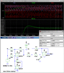
Below is a simulation of a simple single-supply precision full-wave rectifier into a Bessel 2nd-order Sallen-Key 10Hz low-pass filter. It has a ripple of less than 1mVpp with a 1Vpk 200Hz signal. The settling time for a change in the signal level is about 100ms.

It uses a single quad LM324 op amp package. The filter was designed using the free Filter-Pro software from Texas Instrument.

Rectifier with Filter.gif
 
Last edited:
Very nifty full wave rectifier topology, crutschow. I had seen and used other FWR topologies, but this is very straightforward.
 

Very nifty full wave rectifier topology, crutschow. I had seen and used other FWR topologies, but this is very straightforward.
Yes, I've also seem many variations of full-wave precision rectifiers and this is one of the simplest, requiring just two op amps, 3 resistors and 1 diode. And it only requires a single supply (with a single supply op amp of course). It's rather interesting the way the second op amp converts the first op amp to either an inverter or a follower depending upon the input waveform polarity.
 

Status
Not open for further replies.

Similar threads

Part and Inventory Search

Welcome to EDABoard.com

Sponsor

Back
Top