Continue to Site

Welcome to EDAboard.com

Welcome to our site! EDAboard.com is an international Electronics Discussion Forum focused on EDA software, circuits, schematics, books, theory, papers, asic, pld, 8051, DSP, Network, RF, Analog Design, PCB, Service Manuals... and a whole lot more! To participate you need to register. Registration is free. Click here to register now.

Ceramic capacitor current rating

Status
Not open for further replies.

mrinalmani

Advanced Member level 1
Joined
Oct 7, 2011
Messages
463
Helped
60
Reputation
121
Reaction score
58
Trophy points
1,318
Location
Delhi, India
Activity points
5,285
What is the ripple current capability of ceramic capacitors?
I am aware that there is no such limit imposed by the material of the capacitor itself (unlike electrolytic capacitors)
The limit depends solely on the temperature rise, which in turn would depend on the package size of the capacitor.
Even an approximate figure would be greatly appreciated.
Thank you
 

It is closely related with the ESR (equivalent series resistance) of the cap, lower the resistance higher ripple current it can absorb. Because this resistance puts thermal limits through the caps.
 

You'll find current rating numbers in some individual data sheets from major manufacturers.
 

I think most ceramic caps are so low in value that you can't
get significant ripple current through them at their rated
peak voltage. We worried about ripple current ratings on
our few-hundred-uF tantalums (and burned some) but never
saw any problems with even 47uF ceramics. Perhaps because
they are dry, sintered and there's nothing to boil - only
fusing, electromigration or thermal cycle stress cracking
are likely failure modes for overcurrent.
 

I think most ceramic caps are so low in value that you can't get significant ripple current through them at their rated peak voltage.
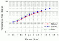
I know many designs where you definitely need to care for ceramic capacitor's AC current rating. Below a datasheet curve of a 47u/10V 1812 X5R capacitor. 4A@100 kHz corresponds to about 0.4 Vpp ripple voltage.


Presently, capacitor manufacturers are promoting ceramic bus capacitors for high voltage, high switching frqeuency power electronics.
 
Presently, capacitor manufacturers are promoting ceramic bus capacitors for high voltage, high switching frqeuency power electronics.

This is very interesting... for PFC converters perhaps?
Wonder how much more expensive are compared to aluminun caps for these applications.
 

That graph above provides a good start point. As expected, current ratings are much higher that their electrolytic counter parts. This is what I was exactly searching for (RMS @ 100kHz)

- - - Updated - - -

There is still one major difficulty.
Ceramic capacitors are non-polar. Why then are their ratings in terms of DC Voltage, and not AC?
I am aware that DC link film capacitors (polypropylene), although non-polar, have a lower (typically 50% lower) AC voltage rating than their DC ratings. Does the same apply to ceramic capacitors. If yes, then what is a typical difference between AC and DC voltage ratings of ceramic caps?
Thank you
 

The peak voltage on a sinewave is 41% higher than its RMS value.

For voltage withstanding, it is the peak voltage that matters.
 
Unfortunately it does not appear to be so straight forward. Consider the datasheet of VISHAY 2.2uF capacitor attached below
Capture.PNG

There is a huge difference between AC and DC capability. In fact I came across a datasheet that clearly states that the absolute maximum ratings are intended for "non reversing" waveform.

Does anyone have an idea about the difference between AC and DC voltage capability of ceramic capacitors? Please help.
 
Last edited:

"In fact I came across a datasheet that clearly states that the absolute maximum ratings are intended for "non reversing" waveform."

Can you post a link to that datasheet? It may have certain specific material specifications (like electro striction) which may cause damage with large applied electrical fields
 

I see this specification at Muarata:

When AC voltage is superimposed on DC voltage, VP-P or VO-P, whichever is larger, should be maintained within the rated voltage range.
"VO-P" obviously refers to the absolute peak voltage in this case. Apart from the question about the theoretical reasoning behind the Vpp,max = Vdc,max specification, the numbers are similar to common specifications for film capacitors, as marked in the Vishay PP capacitor data in post #9. Ceramic capacitors are generally capable of withstanding AC voltage, but with considerable derating compared to DC voltage, besides the limitations resulting from AC maximum current.

It should be mentioned that the voltage strength calculations related to creepage and clerance distance are comparing DC with Vp rather than Vpp of AC voltages (e.g. in EN61010), in so far there's a big difference to capacitor voltage ratings.
 
So does that translate to... the maximum "swing" ie.\[\Delta\]V be limited to the DC voltage rating? I went through some other datasheets and this method turns out reasonably close in predicting the AC ratings. But however consider the datasheet attached below. It states a much larger scaling factor. And also states that the capacitor is intended for "non-reversing" waveforms.
Capture2.PNG
There appears to be no direct translation between AC and DC ratings or am I mistaken?

I am looking for an appropriate capacitor for series resonance tank for an inverter. Since this will now become an off topic discussion for this thread, I am starting a new thread "Selecting resonance tank capacitor". Please help.
Meanwhile, any feedback about the AC performance of ceramic capacitors (which are by nature AC but unfortunately rated in DC) will be appreciated.
Thank you
 

The "non-reversing" waveform specification is quoted from a datasheet of a dedicated DC-link capacitor family. I think, it's probably misleading to relate AC magnitude to polarity in case of film capacitors. The specification isn't founded by other Epcos publications e.g. the general technical informations. But as a matter of fact, foil capacitors are designed for different applications, with focus either on DC, AC or pulse rating. The "DC link" capacitors are intended for applications with moderate AC voltage load.

The Epcos technical information explains that AC voltage rating is primarly limited by internal "corona" (partial) discharge at discontinuities in the dielectricum. In other words, a DC link capacitor is optimized for high energy density (and additionally low inductance) with reduced requirements for partial discharge immunity.

For applications like resonant converters, a dedicated AC capacitor with high AC current rating/low ESR would be chosen, e.g. Wima FKP 4 and MKP10 or Kemet R73 and R76. For extreme current requirements, look at GTO capacitors.
 
Status
Not open for further replies.

Similar threads

Part and Inventory Search

Welcome to EDABoard.com

Sponsor

Back
Top