Welcome to our site! EDAboard.com is an international Electronics Discussion Forum focused on EDA software, circuits, schematics, books, theory, papers, asic, pld, 8051, DSP, Network, RF, Analog Design, PCB, Service Manuals... and a whole lot more! To participate you need to register. Registration is free. Click here to register now.
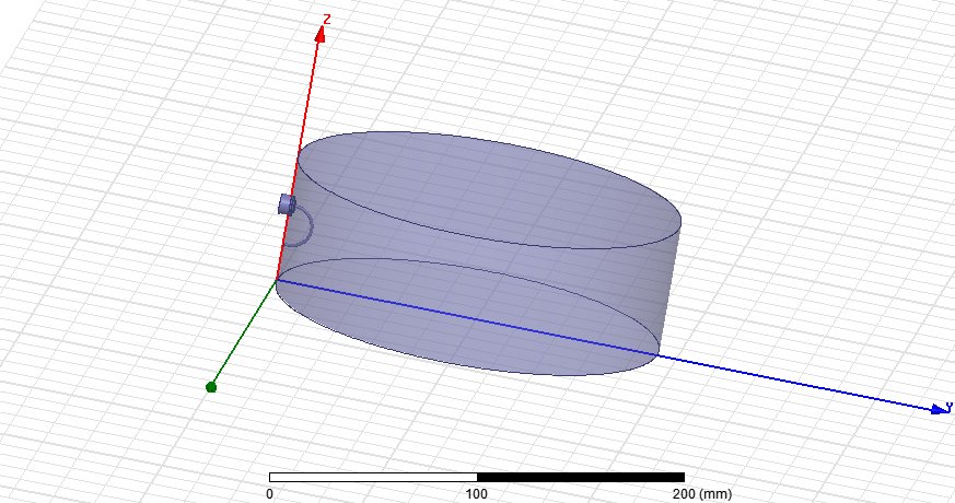
Trying to solve cylindrical cavity in driven modal solution type I ran into huge problems. Im not good in HFSS and think that problem in feeding.
Resonance value is too low. Need any help. :???:
Hi, Iam working on a project to build a cavity filter at 1.8GHz. Iam also facing problems with usage of ports and driven modal solution. Please help if you can.
To understand cavity resonators you must learn how various modes are excited, then you can solve your problems.
Find Harvey:Microwave Engineering, ~1960 or another book on resonators.
Trying to solve cylindrical cavity in driven modal solution type I ran into huge problems. Im not good in HFSS and think that problem in feeding.
Resonance value is too low. Need any help. :???:
Assuming that all your boundaries, material, and excitation ports are set up correctly, you should first take a look at the smith chart around your expected resonant frequency and determine if the external coupling is over or under coupled (also ensure that you have a fine enough sweep as these cavity resonators have significantly high Q-narrow BW). Then, change the input loop radius to decrease or increase coupling to achieve the desired critical coupling. With this loop feed and cavity design, you will excite the TM010 mode. Good luck
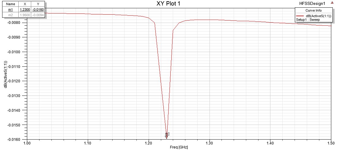
Attached you will find the modified file. Three lowest resonances are 1.224, 1.950 and 1952 GHz. By selecting the dimensions and the location of the input/output probes you can select the mode you want to couple into. I added the second wave guide port to show the resonator response. You can measure the -3 dB bandwidth of the resonator and will find the external coupling Qe. By changing the input coupling element dimensions you will see the effect to Qe.
Also I added the E-field plots of three lowest modes. There you can see the field behaviour and can find the best place to place the coupling loop or probe.
I hope you will get some idea how to work with the cavity.
This site uses cookies to help personalise content, tailor your experience and to keep you logged in if you register.
By continuing to use this site, you are consenting to our use of cookies.