Continue to Site

Welcome to EDAboard.com

Welcome to our site! EDAboard.com is an international Electronics Discussion Forum focused on EDA software, circuits, schematics, books, theory, papers, asic, pld, 8051, DSP, Network, RF, Analog Design, PCB, Service Manuals... and a whole lot more! To participate you need to register. Registration is free. Click here to register now.

fun ideas for 110Vac to 190Vdc, 2.4kW?

Status
Not open for further replies.

acannell

Junior Member level 2
Joined
Apr 16, 2012
Messages
23
Helped
3
Reputation
6
Reaction score
3
Trophy points
1,283
Activity points
1,630
I need to make a power supply to convert 110VAC 60hz to 190Vdc @ 12.5A, about 2.4Kw.

Please dont try to dissuade me..I've wanted to make a power supply and get into SMPS design for years and I've never had a good reason to until now. Its now or never!

I am an EE with lots of practical design experience in light duty commercial circuitry but nothing as sophisticated as an SMPS from scratch, especially a multi kilowatt one. I do appreciate how complex it is and it is not a task to be taken lightly. But I've wanted a chance to get my hands dirty in SMPS. I'm not in a rush and I don't mind if this takes a couple years to get right. Its for enjoyment and learning.

This will be to power the spindle of a CNC mill. The spindle motor is BLDC, and has a spindle amp which controls it. So this power supply will really connect to the spindle amp.

Right now, the spindle amp power supply is generated as follows: 220VAC single phase to primary of large 3kw transformer, secondary is 110VAC which gets rectified and filtered to about 160Vdc unregulated. That gets fed directly to the spindle amp. This isnt my hobby design or something, this is a commercially made mill and thats how its made, and its worked great for about 20 years!

The mill has a maximum speed of 7000 rpm. The manufacturer tells me that I can get it to safely go to 10000rpm if I can somehow get 190Vdc to the spindle amp instead of the 160Vdc. So thats the reason for this.

I notice the folks at diysmps seem to make power supplies like this regularly and I can probably find some designs to learn from there.

But I'd like to know if there are any other ways to skin this cat? I just need the 180V to 195V at about 12.5 Amps. I can use a linear regulator to keep the voltage from exceeding 190V since thats the max temperature the spindle amp can take. So I think the output just needs to be at least 180V and up to 195V and we are good.

Is there another realistic way to do this besides SMPS? I'm up for anything.
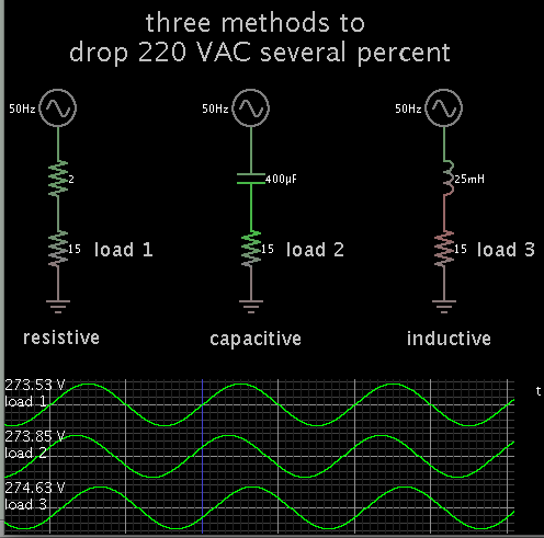
 

Suppose you could drop the mains AC several percent?
Not necessarily with a resistor or capacitor. That would require extremely robust components.

How about with an inductor? Because you are drawing several amperes, you can use about 26 mH.

Here's a simulation showing how it might work (theoretically).

1866524800_1399155977.png


The scope labels show peak voltages. So 220 Vac (nominal) is dropped to 193 Vac.

There is something to watch out for: If your current draw were to go down, voltage will soar.


this is _exactly_ the kind of suggestion I was hoping for....alternatives to SMPS seem really interesting and are fun to discuss

unfortunately the 12.5 amps is definitely not drawn continuously and can vary from 0A to 12.5A, or even higher for a few seconds

and also, the 220VAC is only available on the other side of the isolation transformer (the primary i.e. mains) ..so I would break the isolation if I dont use the 110VAC output secondary of the transformer. so if we want to use 220VAC directly its gotta have its own transformer..which is going to be big and expensive since it will need to be a 2kw one.

at first I didnt understand why they designed the mill to have a 160VDC power supply and stuck at 7000 rpm when they could have 10000 rpm (which is a HUGE selling point for mills) by making it 190VDC..

then I realized that they basically didnt even have to design a power supply if they stuck with 160VDC..its just a bridge rectifier and a couple caps..much cheaper, smaller, and simpler than a SMPS the would need to do the 190VDC..

so really if the motor was 10000 rpm at 160VDC it would be best..but I guess they couldnt find one that met all the other specs and did that..

but it does make me wonder if there is just some way to pull this off...

its frustrating because all that energy is sitting there it just needs to be slightly different. the power is definitely there at least. the 110VAC secondary can supply at least 12.5A if not quite a bit more..definitely 2hp worth because thats what the mill is rated at, and I believe that is spindle output power so the electrical power should be above that by some amount

i have to imagine there is some way to do this..how would they have done this before SMPS, say 1960?
 

using an autotransformer?

ooooh...nice

question now is, can I somehow make one myself?

at least this should be an easy target to research..."need auto transformer, 110VAC to 134VAC, 2.5kw"
 

I do not know where you live, but I think here in Italy a single unit of a custom made 2.4KVA (single phase) autotransformer should not cost more than 200 Euro (even less).
BTW, I have never wound by myself such kind of transformer.
 

I need to make a power supply to convert 110VAC 60hz to 190Vdc @ 12.5A, about 2.4Kw.

But I'd like to know if there are any other ways to skin this cat? I just need the 180V to 195V at about 12.5 Amps.

Right now, the spindle amp power supply is generated as follows: 220VAC single phase to primary of large 3kw transformer, secondary is 110VAC which gets rectified and filtered to about 160Vdc unregulated.

The only way to achieve this nicely is for a dedicated switch mode power supply. At 2.4kW this is a job for a seasoned engineer with lots of experience.
You can buy stuff off the shelf with unity power factor input, e.g. 48V telecom power supplies at 20A each, put three in series (inputs go to the mains, 110Vac or 220Vac, assuming you get the ones with universal input), adjust each one for 55V say, giving you 165V at 20A current limited.
Regards
Orson.
 

So currently it looks like a winner topology might be:

boost converter
with PFC (to improve EMI and reduce input current peaks)
regulated (to keep things at 185V)

It looks like ucc28019 might be a good controller for this. It has a detailed design calculator from TI and is only 8 pins.

I'd still like to find an existing design that is close to what I need so I can analyze it and tweak it.

On the other hand, designing something from scratch using something like the ucc28019 might be a great way to accomplish the goals here, i.e. meet the specs, learn, and have fun doing it too.
 

ooooh...nice

question now is, can I somehow make one myself?

at least this should be an easy target to research..."need auto transformer, 110VAC to 134VAC, 2.5kw"

Making an autotransformer from a "normal" TRANSFORMER IS PLAIN EASY.

1- Take a 110 to 24 volt transformer. On the primary leads, label one "dot", and the other one "no dot".
2- Connect together one of the secondary leads to the primary "dot". Leave the other secondary open.
3- Apply 110v between the primary "dot" and "no dot".
4- Measure the voltage between the primary "no dot", and the open secondary lead.
5- If you get 134 volts, that is it! If on the other hand, you get 86 volts, de-energize the circuit, reverse the secondary leads and repeat steps 3 and 4.

Now, the the autotransformer's total output current is the secondary rated current. So you will have to find a 110/24 Vac, 19 amp transformer. Plitron has a transformer that may match your requirements: model 087060201.
It has two secondaries that must be paralleled to obtain the current rating. Once paralleled, treat it as an individual secondary for the experiment above.

this is great info thanks!

why is the current rating of the secondary all that matters? i would think the weakest link would be the primary in a 110 to 24, since the primary would be designed to handle less current than the secondary right?
 

Correct
The autotransformer only transforms a portion of the power, and the remainder of the power flows conductively thru the windings.
 
Correct
The autotransformer only transforms a portion of the power, and the remainder of the power flows conductively thru the windings.

ahh..now that is a key piece of information sir... thanks! I almost have a solid mental model of autotransformers. Is this correct:

if we imagine a "primary" which is just a coil across mains, and then insert a core into it, we can see that the entire core becomes magnetically energized.

and we can see that if we have our secondary connected directly to the primary on one end, and on the other end at a point along the primary coil, that as we move that point towards the bottom we get approach 0% volts and as we move it towards the top we approach 100% volts (of mains).

now we extend the core, and make the primary longer to match it, but leave the point where primary connects to mains stationary we now have a primary with some length that is above where mains attachs to it.

now if we move our secondary "tap" above the primary mains "tap" we see the voltage continue to go up beyond 100% mains

it seems at this point in the thinking that we have to consider phase differences between the magnetic field and the voltage in order to explain what happens..is that correct? in a two winding xfrmr its easy to just see things as number of turns cutting through a shared field, but with the auto xfrmr it seems a little more esoteric.

where did the 19 amps come from? I think someone else mentioned 20 amps but actually I only need about 10 amps. does that mean I just need a 110 to 24 @ 10 amps?

MAN...just a few months ago I threw away a huge transformer from a harbor freight battery charger/starter...I had been keeping it around for about a year and I finally just said "the heck am I doing keeping this heavy piece of junk around"..and now look it would have been perfect..ARGHHHH why cant I be better at hoarding?

id still need some kind of linear regulator or overvoltage protection because I will be operating things so close to maximum..but if I get all this to work at 180V instead of 190V and just add the OVP to turn on at 190V maybe it will all work out..

- - - Updated - - -

aha..

so check this out on ebay:

"TRANSFORMER - STEPDOWN - GE - 0.5 KVA 120/240 V to 12/24 V"

**broken link removed**

and

"toroidal transformer AC 220V,110V --> output AC 24V 10A"

**broken link removed**

the toroidal one is more like the one you suggested right? but i wonder if the other one would work..would save $30 I could use towards the linear regulator or whatever
 

Autotransformer is not isolated. I would use a 24V/12A transformer from an old 300W UPS and put its secondary in series in phase with the existing transformer ahead the bridge rectifier. It will raise extra 30V. These transformer has centre tap so there can be two positions available, like 175V and 190V. There is another surplus 35V transformer available, from an audio amplifier. A triac based phase angle control can make it with variable output.
 

2500 watt divided by 134 volt (your numbers) equals 18.656 amps. Rounded off to 19 amps.

Either one could work.

And yes indeed, as the previous poster indicated, an autotransformer does not offer isolation.
 
Last edited:

As OP poster wrote:
Right now, the spindle amp power supply is generated as follows: 220VAC single phase to primary of large 3kw transformer, secondary is 110VAC which gets rectified and filtered to about 160Vdc unregulated.

There is already the insulation made from the step down transformer (220Vac->110Vac).
The autotransformer must be connected AFTER the first transformer.

BTW, I really do not understand the suggestion to use an old 300W UPS transformer: in almost EVERY case, those transformers are built for DISCONTINUED usage... And 300W is a bit too low for the OP requirements!
 

Status
Not open for further replies.

Similar threads

Part and Inventory Search

Welcome to EDABoard.com

Sponsor

Back
Top