Continue to Site

Welcome to EDAboard.com

Welcome to our site! EDAboard.com is an international Electronics Discussion Forum focused on EDA software, circuits, schematics, books, theory, papers, asic, pld, 8051, DSP, Network, RF, Analog Design, PCB, Service Manuals... and a whole lot more! To participate you need to register. Registration is free. Click here to register now.

Where to find design guide of photoelectric sensor

Status
Not open for further replies.

simbaliya

Member level 4
Joined
Feb 1, 2011
Messages
74
Helped
0
Reputation
0
Reaction score
0
Trophy points
1,286
Activity points
1,943
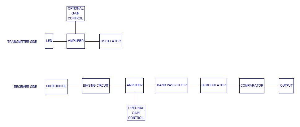
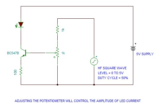
I have been looking for detailed design guide of photoelectric sensor online, but can only found some basic design ideas. Does anyone know how to systematically design a photoelectric sensor with controllable sensitivity? Or tells me where I can find the materials to read. Appreciate if someone can help!
 

What do you mean by photoelectric sensor? The sensor which use photoelectric effect?

Photoelectric effect is something like UV is falling upon metal and metal is emitting electrons. And the sensor using this principle has a vacuum glass tube with two electrodes inside.

Do you want design guide for this?
 

Hi simbaliya, You need to search with the sentence "IR proximity sensor" and hope you will get many ideas.

To make a sensor as shown in the video, you can use the part GP2Y0A21YK then use opamps then two transistors (NPN and PNP) for the final dual outputs.
 
Hi ahsan, can you provide a system level schematic of IR proximity sensor, which indicates how does the op amp, ADC, LED, photodiodes and microcontroller connect to each other?
 

Hi simbaliya,

Hi ahsan, the microcontroller sends PWM signal to control the LED, or an oscillator can do the same work.

Yes,exactly. Besides microcontroller can do the job of comparator also. So I will use the term oscillator,comparator etc..in the functional block diagram. Later you may decide implementing the blocks using microcontroller.

See the block diagram below.


You can control sensitivity by adjusting the gain of any side amplifier.
Most of the blocks of Rx side may be available in a single chip. You can check the part TSOP/TSSP4038. Besides you can use PLL ic like NE567 in place of BAND PASS FILTER + COMPARATOR block too.
 

Thank you for the block diagram, ahsan. I have several questions to ask:

1. How to adjust sensitivity range by adjust op amp gain? In my opinion, the sensitivity range can be adjust by change the transmitter LED current (or duty cycle?), or by change the bias condition for receiver op amp.

2. I do not get it the need of bandpass filter, de-modulator and comparator in the receiver.

3. You mentioned dual outputs (PNP and NPN), may I ask why need dual outputs.

Not sure my understanding of IR proximity sensor is correct, let me know if I am wrong: In the transmitter, a PWM signal is fed in to an op amp (or comparator), followed by a driver, to control the on/off of the npn transistor (with ability to drive large current ) at the output, which eventually control the LED switching. In the receiver, when the IR light is detected by photodiode that is reverse biased, dark current generates voltage drop thru a resistor, this voltage drop is detected by an op amp, a high output is generated at the op amp output to switch on the npn (with large current drive ability), which eventually turn on the LED in the receiver. The on/off of LED in the receiver indicates whether an object is presented in the sensable range.

In my above concept, there's no bandpass filter, de-modulator, and comparator in the receiver, and there is only a npn output.

Actually we need to transmit/receive high frequency(HF) IR signal to make this communication secured from all other IR sources like window,lamp,heater etc. Otherwise false operation may happen. Controlling LED intensity using PWM is not the main reason.

Bandpass filter(BPF) is tuned at the frequency of the transmitter, so it is ensured that the output from BPF is the signal which is transmitted from the transmitter.

Output from the de-modulator is a DC voltage which is propotional to the amplitude of the HF signal. It can be an envelope detector circuit.

We need ON/OFF output (digital) from receiver. Output of de-modulator is a DC signal which varies according to the amplitude of the received HF signal. So it is analog signal. Comparator will convert the analog signal to digital ON/OFF signal by compare it with a reference voltage. It is better to add some hysteresis also. Basically comparator is an one bit A/D converter.

According to desired output type, output of the comparator will go to NPN or PNP transistor. Some indutrial PLC needs NPN sensors, some PLC needs PNP sensors. As a result, in the video they developed universal output sensor which has both NPN and PNP type output.

3. You mentioned dual outputs (PNP and NPN), may I ask why need dual outputs.

I just said it. You may ask again.

2. I do not get it the need of bandpass filter, de-modulator and comparator in the receiver.

I just said it. You may ask again.

1. How to adjust sensitivity range by adjust op amp gain? In my opinion, the sensitivity range can be adjust by change the transmitter LED current (or duty cycle?), or by change the bias condition for receiver op amp.

From transmitter side, without PWM control (constant duty cycle, say 50%), we can adjust sensitivity by controlling LED current amplitude. If we drive LED with a transistor then we can control the gain (here I mean output current divided by input voltage) of the transistor switching circuit to adjust LED current. See the picture below


We can also use PWM method to control average current of LED to adjust sensitivity. PWM method should work because output of BPF is the fundamental frequency whose amplitude varies according to PWM.

From receiver side, we can adjust sensitivity by adjusting the gain of the amplifier, because the amplifier is amplifying the HF ac signal and amplitude of this ac signal is detected after BPF to trigger output. Bias circuit gives DC bias to photodiode and there is a DC block capacitor at the input of the amplifier.
 
Hi ashan, thank you for your help all the way. In fact I was having interview with a German sensor design company, and I am lucky enough to enter the last round of interview session. If things go well for the last round interview I will receive offer within next week. My concern now is I need to know the outlook of a career as an electronic engineer working in IR proximity sensor design, so that I can make up my decision whether to take the offer (if offered). Would you mind share your thought, ahsan?
 

Hi simbaliya,
In the field of industrial automation and control, sensors are very important part. Without these, electronic automation is almost impossible. Besides sensors are consumable items too. They stay in the production process area/field where level of temperature, vibration, humidity, chemical dust etc.. are high and they get damaged more frequently than other items like PLC or HMI which stays inside control panel (sometimes with air conditioner).
Sensors are very common things and also interesting. Career as a sensor designer is interesting too.
I know few german words these are
1. Spannung = means voltage
2. Strom = means current
These word meanings may help you to avoid sensor damage by applying over voltage or over load.

Hi ashan, I just signed employment contract with the Geman sensor design company and will start my career as a sensor design engineer focusing in electronic area. Without you help I may not get the job, thank you very much, and thank you again. May I always come back and ask you questions if I face difficultes in the job?
 

Status
Not open for further replies.

Similar threads

Part and Inventory Search

Welcome to EDABoard.com

Sponsor

Back
Top