Continue to Site

Welcome to EDAboard.com

Welcome to our site! EDAboard.com is an international Electronics Discussion Forum focused on EDA software, circuits, schematics, books, theory, papers, asic, pld, 8051, DSP, Network, RF, Analog Design, PCB, Service Manuals... and a whole lot more! To participate you need to register. Registration is free. Click here to register now.

WHy BJT Drive Mosfet

Status
Not open for further replies.

ycbq999

Newbie level 2
Joined
Apr 19, 2014
Messages
2
Helped
0
Reputation
0
Reaction score
0
Trophy points
1
Activity points
13
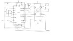
I an just a new grad. This motor controller typical diagram is quite confusing for me. Why does it use two bjts to drive top two mosfets? And to be honest, I do not see how do these two bjts work to turn on the mosfet. I hope someone can explain to me with patient. Thank you.
 

Attachments

  • Untitled.jpg
    Untitled.jpg
    75.8 KB · Views: 79

The BJTs are buffers they work as emitter followers on the AOUT1 pin, when its low the bottom transistor has a b-c short so its emitter, sits at Vb + .8V and when VOUT1 is high its the other way around and the top transistors emitter is at Vb - .8V. The gate input capacitance of a FET is very high and its important that it is discharged rapidly, to stop a "top" FET being held ON by the voltage on its gate capacitance when the "bottom" FET is switched on.
Frank
 
HI Chuckey, thank you for your reply. It is really helpful. There is a particular part I am still not sure of. It is the zener diode and diode in parallel with a resistor connected between Base and Collector of the top BJTs. Would that make the Vb constant no matter AOUT1 on or off?
 

The best I can do is that the zener + diode sets the junction of the bases to 1/2 of Vcc. The diode is for temperature compensation. In the absence of pulses from Aout, both the BJTs are off, the top one conducts when its base is at 1/2Vcc +.8, the bottom when its base is at 1/2Vcc -.8. AS Aout has a finite rise and fall times to its edges, this gives a dead band around 1/2Vcc where both BJTs are off. The effect is that the output at the emitters is a pulse that starts later and finishes earlier then Aout. Its more protection against the top FETs being on when the bottom FETs are on.
Frank
 
Status
Not open for further replies.

Part and Inventory Search

Welcome to EDABoard.com

Sponsor

Back
Top