Continue to Site

Welcome to EDAboard.com

Welcome to our site! EDAboard.com is an international Electronics Discussion Forum focused on EDA software, circuits, schematics, books, theory, papers, asic, pld, 8051, DSP, Network, RF, Analog Design, PCB, Service Manuals... and a whole lot more! To participate you need to register. Registration is free. Click here to register now.

How do negative and positive feedbacks work at the same time?

Status
Not open for further replies.

jeongminjeon

Newbie level 3
Joined
Apr 16, 2014
Messages
3
Helped
0
Reputation
0
Reaction score
0
Trophy points
1
Activity points
23
two feedbacks.png

Hi,
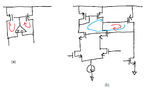
I found many times OPAMPs are used to force two node voltages the same like picture (a).
I also found that two loops like in (b).
When there are both the negative and the positive feedback loops in the circuits, what happens?
How do I make sure the positive loop is stable? Do not the OPAMP inputs in (a) swing rail to rail?
Do the two loop cancel each other?
If the positive loop gain is larger somehow by systemic error, will the circuit be unstable?

Thanks.
 

Attachments

  • two feedbacks.png
    two feedbacks.png
    22.1 KB · Views: 55

The circuit operation depends on overall negative feedback, respectively the negative feedback being stronger than the positive.
 
Thanks FvM.
The circuits around positive and negative loops are symmetric or balanced in (a) and (b).
The goal of using OPAMP in (a) is making two PMOS bias condition the same. Consequently both the loop gains will have the same gain.
So how can the negative loop be dominant in (a) and (b) without losing balanced operation?
 

The circuits around positive and negative loops are symmetric or balanced in (a) and (b).
The circuit looks like an incomplete snippet from a wellknown PTAT design, e.g. Razavi Figure 11.18, which implements an asymmetrical load.

I presume you didn't realize the asymmetry, or copied the schematic incompletely. If it's actually symmetrical, the circuit can't work.
 
Thanks FvM,

circuit (a) is for PTAT and you are right. Negative loop has more gain by factor of (R+1/(K*gm))/(1/gm).
circuit (b) loops don't have gain due to tail current source for the common mode input. My bad and it is OK.

Thanks.
 

Status
Not open for further replies.

Part and Inventory Search

Welcome to EDABoard.com

Sponsor

Back
Top