Continue to Site

Welcome to EDAboard.com

Welcome to our site! EDAboard.com is an international Electronics Discussion Forum focused on EDA software, circuits, schematics, books, theory, papers, asic, pld, 8051, DSP, Network, RF, Analog Design, PCB, Service Manuals... and a whole lot more! To participate you need to register. Registration is free. Click here to register now.

Mercury UPS Power Problem

Status
Not open for further replies.

eeHassan

Member level 2
Joined
Jan 28, 2011
Messages
52
Helped
0
Reputation
2
Reaction score
1
Trophy points
1,288
Location
Lahore, Pakistan
Activity points
1,615
Hi everyone,
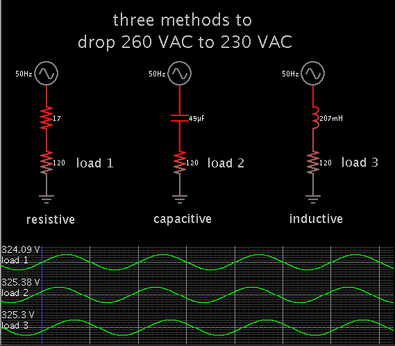
I am using Mercury 1000va inverter powered by 12V battery for storing power in case of power failure (which is quite common in Pakistan). However I am facing a problem that is when the main supply voltage goes above 250V the ups goes into backup mode i.e instead of charging the battery it starts draining it and keeps running like this until the voltage comes down to 230V again. In my house the main voltage is normally above 240V and sometimes even 260V so my UPS does not charge the batteries. I need to use some simple and cost effective techniqe to reduce the input voltage only for the ups may be by connecting something in series etc...
Any effective suggestions please
 

usually AVRs will reduce as well as increase voltage. You might want to check the AVRs to see which is the best at reducing the voltage.
 

One time our house voltage rose to 130 VAC after a blackout. (Normal is 115-125V.)
My inverter would not charge the batteries. Apparently it needed for the house voltage to be within a certain range.

I tried a makeshift strategy to reduce the voltage. I ran a long extension cord to the inverter. I plugged in both the inverter and a space heater. This worked to bring down voltage at the inverter, so that it charged the batteries.

The extension cord was light duty. It heated up a little, due to carrying heavy current.

- - - Updated - - -

may be by connecting something in series etc...

The obvious way is to install a resistive load in series. Possibly a length of nichrome wire from a toaster or space heater.

It will be best if you can make it adjustable. A metal clamp or something similar. This could be trouble-prone (particularly if it sparks). You should install safeguards to prevent fire, and contact with high voltage.

Other components you can try putting in series are a capacitor, or an inductor. Values must be custom-adjusted for the load. It is easy to make a mistake. You should monitor what's going on, and make sure that no part gets exposed to overly high voltage.

Suppose your inverter draws 2A while charging the batteries.
This simulation shows which values will drop 260 VAC to a normal level.


In the case of a capacitor, it must be non-polarized type, and rated for the maximum voltage it will be exposed to.

In the case of an inductor, it may be possible to construct an adjustable inductor. It must have a substantial amount of metal in its core.

A safer way is an auto-transformer. (I believe this is what post #2 refers to.) It has the secondary connected to the primary, and is less expensive than a transformer. It has taps which yield different volt levels. It must be rated for your voltage and current needs.
 

I thought about it but the problem is UPS not only has to charge batteries other house load i.e fans and lights also comes through it and that load is constantly changing so the voltage will change with the load if there is anything like the formation above...........
Avr`s are expensive and still no guarantee to work.... most AVRs have isolated neutral of output and ups requires the same neutral as of main supply so it might still not work
 

Get a 230V to 24V 5A transformer. wire the primary to the mains. CAREFULLY attach one end of the 24V to the mains. Switch on the mains and measure the voltage on the loose 24V connection, it will either be 230 + 24 V or 230 -24V. If its the + case, switch of the mains and reverse the 24V connections. Now your mains to the inverter will be mains - 24V. It would be prudent to put the transformer under an insulated screen, in case the insulation of the 24V windings to the core is not very good.
Frank
 

Status
Not open for further replies.

Part and Inventory Search

Welcome to EDABoard.com

Sponsor

Back
Top