Tech_boy
Newbie level 5
Hi guys,
hope this is the right section for this question.
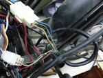
I have this electric scooter which is powered by a pack of 48V batteries feeding a 350W Burshless DC motor. The DC Motor has 3 phases, each having it's respective position sensor (photo attached shows the wires coming out of the motor).
Now I am creating a datalogging system using an arduino Mega 2560. I need to measure Voltage and Current between the controller and the hub motor across one phase and rpm.
RPM - No problems there
Voltage - I'm using a POT to lower the 48V to 5V to input the arduino and that works fine as well
Current - THAT IS THE PROBLEM!
First I placed my multimeter in series with one of the phases, but didn't get any readings strangely enough!
So far I used ACS758 LCB-050B following this tutorial: https://www.dfrobot.com/wiki/index.php/50A_Current_Sensor(SKU:SEN0098)
I managed to read current drawn by a 12V car heater which draw approx. 7A but no success with the brushless DC motor.
I tried a CT but I guess it was faulty .. but still no success
Now I just bought lts 15np by LEM. Didn't have much time to test it but it's the only component that is giving me some kind of readings. However, they don't seem to be consistent .. For example if I try to stop the wheel from turning, I'm don't get a proper increase in current and if I leave the "throttle" at constant speed, the current value varies sometimes. I also introduced a low pass filter.
Anyone can guide me on how to measure current drawn by a brushless DC motor? Maybe someone already did a similar project using arduino or any other microcontroller? Is there anything I should know about controller and brushles motor in electric scooter?
hope this is the right section for this question.
I have this electric scooter which is powered by a pack of 48V batteries feeding a 350W Burshless DC motor. The DC Motor has 3 phases, each having it's respective position sensor (photo attached shows the wires coming out of the motor).
Now I am creating a datalogging system using an arduino Mega 2560. I need to measure Voltage and Current between the controller and the hub motor across one phase and rpm.
RPM - No problems there
Voltage - I'm using a POT to lower the 48V to 5V to input the arduino and that works fine as well
Current - THAT IS THE PROBLEM!
First I placed my multimeter in series with one of the phases, but didn't get any readings strangely enough!
So far I used ACS758 LCB-050B following this tutorial: https://www.dfrobot.com/wiki/index.php/50A_Current_Sensor(SKU:SEN0098)
I managed to read current drawn by a 12V car heater which draw approx. 7A but no success with the brushless DC motor.
I tried a CT but I guess it was faulty .. but still no success
Now I just bought lts 15np by LEM. Didn't have much time to test it but it's the only component that is giving me some kind of readings. However, they don't seem to be consistent .. For example if I try to stop the wheel from turning, I'm don't get a proper increase in current and if I leave the "throttle" at constant speed, the current value varies sometimes. I also introduced a low pass filter.
Anyone can guide me on how to measure current drawn by a brushless DC motor? Maybe someone already did a similar project using arduino or any other microcontroller? Is there anything I should know about controller and brushles motor in electric scooter?
")