Continue to Site

Welcome to EDAboard.com

Welcome to our site! EDAboard.com is an international Electronics Discussion Forum focused on EDA software, circuits, schematics, books, theory, papers, asic, pld, 8051, DSP, Network, RF, Analog Design, PCB, Service Manuals... and a whole lot more! To participate you need to register. Registration is free. Click here to register now.

Light sensor intensity

Status
Not open for further replies.

haitham al-saab

Junior Member level 1
Joined
Aug 4, 2013
Messages
16
Helped
0
Reputation
0
Reaction score
0
Trophy points
1
Activity points
130
Hello every body
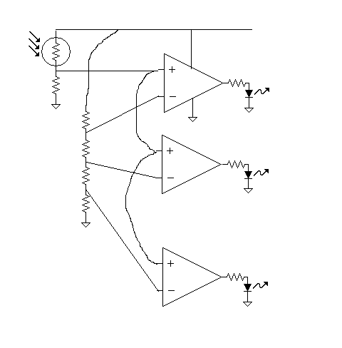
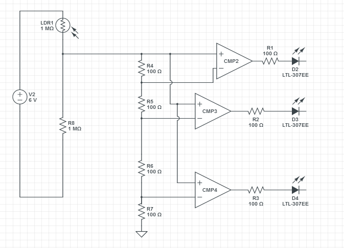
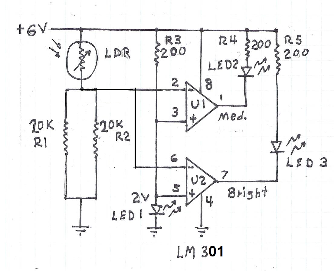
I'm still beginner in designing a circuits I decide to make a light sensor with three leds , If the light R very bright the 3 led will start work if it is less brightness 2 will work and if there is no light just one will work
I know I have to use comparators but the problem I don't have a complete idea or a program to simulate plz help me
thx a lot
 

do you want to use the LEDs as sensors AND as indicators?

it would be much easier to have another device acting as a light sensor

you could use a LDR as part of a 3 resistor voltage divider - with transistors connected to points on the divider - which would turn on the LEDs
 

The eye can see over 10 decades of light intensity, but you may be only interested in a narrow range with 3 levels. Can you specify this?
Also do you need to diffuse the light sensor to detect average light level?

A good design always starts with a good spec. You can surf Google Images for implementation ideas.
 

the photo resistor has 2m ohm in dark and 200 ohm in light
my schematic
2813368300_1397084068.png

the value of the photo resistor has 2m ohm and 2k ohm in room light in dark and 200 ohm in bright light

- - - Updated - - -

my problem with the value of resistors

- - - Updated - - -

In dark one light in room 2 light in mobile flash 3 light
 

my problem with the value of resistors

time to use your favourite spread-sheet!

label the resistors in the resistor voltage divider, starting from the top R1, R2, R3, R4 and their intersection a, b, c

voltage at a is [R2 + R3 + R4] / total resistance

voltage at b is [R3 + R4] / total resistance

voltage at c is [R4] / total resistance


start with a value for R4, then total resistance = R4 / desired turn-on voltage

the desired turn-on voltage is where Vldr > Vc

the rest is simple algebra

I suggest using a spreadsheet because you will probably want to try different values
 

Please don't lough on me I know it is a beginner questions
1- how to find the output of compartor the gain is so high so how can I control it
2- under which condition the comparor will work
3- is compartor saturate like the amplifier which the good value for V+ , V-?
4- from the figure below what is the good value for R8, so that it can open at least one led I try to make it as high as possible but in the good cases it feed the right hand resistor just with 2 V which is not enough to run one led
5-any quick suggestion for the right hand resistors
6-Is there a simulate and good program ?

plz don't be angry I try to make some projects coz I know it is the only way to learn and as I said I'm still beginner
 

WHen (+) input is > (-) input the output goes high and visa versa.

Often there is noise on photo sensors especially from fluorescent lights which pulse light, so one LED may be dim if near the next threshold .
 

I'll use Lm 301 for the compartor
I'm still beginner : (
 

R8 should be grounded.
Many other errors.

100 Ohms is far too low. for R4,5,6

Disconnnect R4 from Sensor and add a pot or pullup resistor, R9 to 6V around 100k to 1M

Then change R4,5,6,7 to choose threshold

such as 100k,10k,1k,100
 
Last edited:

Please don't lough on me I know it is a beginner questions
1- how to find the output of compartor the gain is so high so how can I control it
2- under which condition the comparor will work
3- is compartor saturate like the amplifier which the good value for V+ , V-?
4- from the figure below what is the good value for R8, so that it can open at least one led I try to make it as high as possible but in the good cases it feed the right hand resistor just with 2 V which is not enough to run one led
5-any quick suggestion for the right hand resistors

1 - you don't control the gain of a comparator. It is either is HIGH or LOW.
2 - https://en.wikipedia.org/wiki/Comparator
3 - it seems you are using an op-amp as an comparator, rather than a dedicated comparator. LM301 has a minimum supply voltage of +-5V, but can, I believe only swing to about 2V of the supply voltage, so if Vsupply is +5V, the highest output is +-3V. I suggest, if the LEDs are connected to ground, a voltage supply of between +-6v to +-12V
4 - I suspect your values for the LDR are not correct, anyways I would connect the 'top' of R4 to a stable reference voltage - NOT as you have it now.
5 - all depends on when you want the LEDs to light, but I would start with values much higher than you have now. Say 1K to 10K.

- - - Updated - - -

connect to the top of R4 to between the zener diode and resistor.

V+ --------------------resistor----------------zener diode-------------ground

if V+ is 6V and the zener diode is 4.7V then the resistor would be at least [6 - 4.7]/10mA

The 10mA isn't a fixed number - depends on the zener, but it ought to work with most zeners and still allow a few mA for the voltage divider.


Also, I recommend using a multi-meter and measuring the actual resistance of the LDR - writing down the resistance values for the different light levels.
 
Last edited:

I got this schematic but just one lamp work and the other not
 

I got this schematic but just one lamp work and the other not
[/url]

If you made the suggested changes to your orginal schematic it would be close to this one.

Jumping from one circuit to another won't help. Anyways you don't say which LED lights. It helps to be specific.

Did you measure the resistance of the LDR under different light levels, yet?
 

Using this ladder comparator with somewhat equal values gives you 3 levels in a limited range. THis can be extended to as many as you want by adding more R's to the ladder and more comparators.

Using more log scale values in the resistor ladder will spread out the thresholds like 1,3,10,30,100,300 (K)

Here the R ladder starts at the bottom with 1k,2k,2k,4k , which could be 10k,20k,20k,40k for same.
Another range of thresholds might look like 10k,20K,40k,10k where the top one affects all the lower thresholds.
Then another variation might add 1Vp AC to the top threshold (pin 6 below) so that each LED gradually turns on to full brightness, while the next LED is starting to turn ON.
**broken link removed**
Check Input vs Light vs threshold to determine setpoints for R.
 
Last edited:

Status
Not open for further replies.

Part and Inventory Search

Welcome to EDABoard.com

Sponsor

Back
Top