Continue to Site

Welcome to EDAboard.com

Welcome to our site! EDAboard.com is an international Electronics Discussion Forum focused on EDA software, circuits, schematics, books, theory, papers, asic, pld, 8051, DSP, Network, RF, Analog Design, PCB, Service Manuals... and a whole lot more! To participate you need to register. Registration is free. Click here to register now.

[SOLVED] 74LS74 D flip flop state changing automatically

Status
Not open for further replies.

RohanDey

Member level 2
Joined
Feb 17, 2013
Messages
42
Helped
1
Reputation
2
Reaction score
1
Trophy points
1,288
Location
India
Activity points
1,688
Hello,

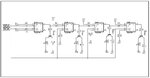
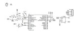
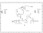
I have a cascaded D flip flop circuit. Schematic attached. I am sending the data and clock pulse from a PIC microcontroller.

What happens is, when the data and clock pulses are sent the leds glow properly as expected. But after a minute or two, the flip flop states get changed automatically and the leds also glows accordingly.

I am not sending any data-clock pulse after the first one. But still the flip flops gets changed.

Please help!
 

Attachments

  • flip-flop.JPG
    flip-flop.JPG
    43.3 KB · Views: 234

Noise pulses ( eg ESD) on long wires on the output or ground can feedback internally. Decoupling caps on chips are essential, sometimes a buffer, although the transistor ought to act as a buffer. So My guess is conducted or radiated noise on long wires.
 

Yes, I am using long wires, about 4 inches long, for data and clock. Actually my PIC is on an EVK and the flip flops are on a bread board.

So do you suggest that I put all the things on a PCB and then try?
What about decoupling caps? Should I use them? Where should I connect them?

Thanks
 

at least one ceramic 0.01 to 0.1 uF is typical. close to chips from a clean supply, then beware of transient environmental noise like welders or line noise or triac dimmers. IF there is radiated noise, twisted pair helps reduce differential noise, but 4" is fairly short. IS this battery operated?

When in doubt, a logic probe or scope probe with a short ground lead and manual trigger is sometimes needed to find the source of spurious noise. Beware of source impedances and stray coupling of magnetic or electric field impulses or dynamic loads.
 

No it is not battery operated. I am using a transformer based linear power supply. I will add the caps and check what happens.
 

Hello SunnySkyguy,

I tried with ceramic caps of 0.1uF. I connected the caps between VCC and GND lines and to each flip flop's data-gnd, and clock-gnd pins. But the problem still exists.

Whenever I switch ON or OFF an electrical connection (Fan or Light) in my room, the flip flop changes states. Any idea how to fix this?

Thanks
 

Perhaps the LEDs are the antenna picking up large electric field transient.

Without big picture of your layout and connections, I can only guess how to best protect it.

If everything is floating with respect to ground, adding a ground connection can often suppress stray noise. ALso using a torroidal common mode choke with the long wires to LEDs wrapped with a few turns around the torroid or some CM choke.

At least you have rules out conducted noise and identified the source as radiated noise.

Another trick is to put a small cap on output Q to identify if the noise is getting in there, (Q has internal input connections)
 

Maybe this is not related with the anomaly you describe, but take into account that the Q ouputs of the flip flops are seriously loaded in your circuit. Current capability of LS TTL's in High state is low and voltage can be bad, then "H" level can be insufficient for the D input.
I would change the output circuit that lights the LED. An easy possibility is put the LED in the colector circuit and increase the Rs from 100 ohms to 10k. Better would be to use the /Q output and a PNP transistor.
Regards

Z
 

I considered the load to be marginal.

If it is a 74LS, the specs are as follows;
Voh= 2.7Vmin @ -0.4mA

Consider Vf=2.0V on Red or Yellow LED @ 20mA and assume Vbe=0.7, with hFE=100 the load current will be limited by the base drive current with Emitter follower transistor.

Also the emitter load current will rise rapidly above Vf=2V or base voltage > 2.7V , but the driver impedance of LS74 rises rapidly above 2.7V as its output is a Darlington, emitter follower for Voh, which has 100R collector current limiting, internally.

Assuming hFE of 100 for the 2N2222 , if Voh=2.7V it can supply 400uA x100 = 40mA to the emitter, and the base resistance of 100R only drops 0.1k * 0.4mA= 0.04V. Which is not much... to worry about, so loading is not excessive.

LED current could be anything from 5 to 40 mA, due to Vf junction voltage tolerances.

20x more current on low state then invert with Common emitter low side drive to LED cathode with current limiting R on collector.

There is a noise susceptibility issue here and one needs to identify if interference is conducted or radiated then determine where the margin is least for ingress and fix that. So far there is insufficient information to track this down.

My last guess was radiated noise from somewhere picked up my long (?) LED lines than conducted back into Q to toggle state every few minutes, but we don't know how interference starts.
 
Last edited:

Sorry for such a late reply. I was stuck up with a different project.

I have setup the entire circuit on a vero/strip board. My new circuit is attached.

Now I have a relay at the output of the D flip flop. I also have a small delay circuit in between the relay and the D-FF output. It is just a requirement of my application. At the output of the relay I have connected a 230V, 60 Watt light bulb.

Normally everything happens as expected. When I give necessary pulse to the D-FF, the relay turns ON/OFF in effect turning the light bulb ON/OFF. But sometimes when the relay is turned off, the D-FF (74LS74) turns ON automatically just after being turned OFF, i.e. it stays OFF momentarily and then the flip flop output 'Q' toggles its state.

I have seen on the oscilloscope that when the relay is getting turned OFF, a noise spike is generated on the DC side. I have attached a photo of it. Here the red line is the VCC and the yellow line is the GND. This noise is seen on all the pins of the D-FF (i.e. data, clock and Q). This spike is reaching voltages up to 30V sometimes, and it lasts about max. 100 to 150 us.

What I understand is because of this noise spike the flip flop is changing state.

I want to know, what are the possible methods/circuits, which I should add to eliminate this noise spike, so that the flip-flop does not change state?

This noise is also reaching my PIC micro-controller's VCC, GND and data pins. Can it damage the IC?

Thanks for reading.. please help!
 

Attachments

  • Noise.jpg
    Noise.jpg
    637.5 KB · Views: 110
  • ff--rel-sch.JPG
    ff--rel-sch.JPG
    24.2 KB · Views: 111

The first thing you should do is to add a resistor from base to emitter(Vcc) on the relay driver PNP transistor. This driver get a marginal base current(voltage) and no defined off signal, only a floating off.
This may cause relay bounce both at ON and OFF.
The 'delay circuit' and the zener diode in the emitter circuit is very iffy. I think this is done to make an increased delay on the output, but the result is as said iffy at the best.
Why do you need this delay?
To get the best performance of the relay you should drive it properly. Since you drive the PNP transistor with only -1.5V and a 10k base resistor, the bleeder resistor to emitter need to be relative high in value.

To rectify this I would have reduced the base resistor (R13)to 680 ohm, and added a 1k bleeder resistor from the NPNs (Q4) collector to VCC. This resistor will turn the PNP transistor (Q5)OFF properly.

I suppose you understand that your delay circuit is working both at ON, and OFF, making the flanks iffy.
 

I need the delay circuit because I am cascading many of these flip flops together and driving them from one source, i.e. data and clock signal. Here if I do not add the delay the output of each flip flop will flicker if I want to change only the nth flip flop state.

I require the delay to happen in both ON and OFF state.

I will change the R13 and add a 1K from the NPN's collector to VCC and try as you say. What about he noise?
 

If this is made as a breadboard with many long wires, you may have a problem anyway.

But, how is your actual circuit as you have built it?
Describe the decoupling capacitors you have used, and where you have placed them in the circuit.

Normally the noise is coming from wires acting as antennas, and/or capacitive coupling between elements, like inside the relay. The noise will come from the sparks generated in the relay contacts, and the inductive spikes from the relaycoil.

That is why it is important to make the power supply as stiff as possible, or with as low impedance as possible, using capacitors, of the right type and value, placed at the optimal places in the circuit.
 

Hi,

I have made the change in my circuit. Instead of the 680 ohm I have put a 1k as I didn't have the 680 ohm with me. And I have also added a 1k bleeder resistor from the NPNs (Q4) collector to VCC.

My entire setup is on vero board. I have three different vero boards each having the same flip flops and relay circuit. The flip flops are cascaded and the vero boards are connected via connectors. I send the data and clock pulse from a PIC.

I have put 0.1uF ceramic caps on the vcc-gnd terminals of each flip flops. I have connected a 230V, 60W light bulb only to the first board.

What happens now is, when the relay with light bulb is turned OFF it toggles the state of the other flip flops cascaded to it. This does not happen every time. Also, this happens only when the 230V light bulb is connected, when I remove the bulb, everything works fine.

I am sure my power supply is pretty stable.

So it seems that it is the noise from the relay that is making the problem. Can you please tell what other options should I try out? Is it a vero board layout issue? Should I use some additional circuitry to handle the noise?

Thanks..
 

Could you make a complete schematics of the circuit you are using, exactly as you have built it, and if possible add a picture of the mockup circuit too. It is important to include all components you use.

How do you control the FFs, from a microcontroller or manually?
 

Yes, an update of your schematic would be nice. After so many posts, your circuit should look very different from when it got started.

Allen
 

EMI issues are based on physics of induction and capacitive coupling and conduction noise spikes.

A veroboard can get pretty messy with inductive grounds, signals and coupling to the high current bulb, which arcs when contacts are opened causing many MHz of resonant spikes, which couple easy thru stray capacitance or induce large inductive voltages across leads and power.

Two methods.

1. eliminate the noise. Use a zero crossing switch triac, and snubber RC filter. Route all spike currents with twisted pairs to reduce unintentional radiation, such as 6 twists per inch with care on line & neutral. Apply small but high V rated film caps across relay contacts. or shield the relay or remove it far enough away from the offending circuit. ( as in cars in the corner under the hood)

2. Improve the target immunity for noise on ; power, grounds and signals Beef up wires, use low impedance battery or power sources, shield the board, use COmmon mode chokes on the control signals ( ferrite 2-hole beads, torroid, clamshell-core etc) add feedthru capacitive filters for in/out signals in the box.

3. Measure transients more accurately with zero length probe ground using the barrel and tip. Or use two probes in A-minus-B for remote signal and ground and wrap both identical probes as twisted pairs with identical short ground clips. When in doubt connect probe tip to ground to ensure flat line , same with 2 probes in A-B connected to same signal, then no stray noise should be observed if done right.
 

I have attached my schematic and photo of the veroboard. The photos contain the assembly circuit also where 2 Relay-FF boards are connected together with the controller board.

I am using the same power (vcc) and gnd line for the relay and the other circuit. Here VCC = 5V. Could this be a problem? Please check and comment.

- - - Updated - - -

1. eliminate the noise. Use a zero crossing switch triac, and snubber RC filter. Route all spike currents with twisted pairs to reduce unintentional radiation, such as 6 twists per inch with care on line & neutral. Apply small but high V rated film caps across relay contacts. or shield the relay or remove it far enough away from the offending circuit. ( as in cars in the corner under the hood)

Your comments are very informative, but sometimes gets difficult for me to understand. It may sound silly but, can you please explain how will a zero crossing triac and a RC snubber will help to remove noise spikes? I have very basic knowledge about triacs and used it only in dimmer application.

Also, about the film caps, I have 104K400 polyester cap. Can I put this value across the relay terminals?

Thanks..
 

Attachments

  • top.jpg
    top.jpg
    357.5 KB · Views: 107
  • assy.jpg
    assy.jpg
    284.3 KB · Views: 87
  • bottom.jpg
    bottom.jpg
    601.6 KB · Views: 118
  • schematic1.JPG
    schematic1.JPG
    61.8 KB · Views: 122
  • schematic.JPG
    schematic.JPG
    57.7 KB · Views: 117

Hi,

cascading the SPI over several PCB is not agood idea.
At least you need a very solid (low ohmic and low inductance) GND connection. Best by GND plane on the pcb and multiple wires from board to board.

There may be noise on the GND that causes your problem.

My hint: Try to use a 20k series resistor from common CLK line to FF CLK input and additionally connect an 1nF capacitor from the CLK input to GND.
This "cleans" the clk line.

Mind to connect all UNUSED inputs of your FF to a valid logical state.

Hope this helps.

Klaus
 

Since you are daisy chaining several modules, you need to decouple each board for itself.

Since you are using the 5V for the relay too, you need to add a electrolytic capacitor on each board, I would think 22-47uF is ok.

In addition you need to add 0.1uF capacitors to each board. A rule of thumb is one for each IC, directly over the supply pins, or as close as possible, and at least one extra. If you are experiencing high frequency noise, you could also add a 0.01uF to the mix.

Running the supply line as you do with 5V, you need a very good connection, with large enough area of the wire.


A practical thing to do, is to make the input and the output connectors for your 'bus' as close together as you can on each PCB. This will reduce the effect of the noise generated on other modules, and the size of the 'loop' for your power lines.

I would personally have at least two leads in your 'bus' for the GND connection, to make the ground stiffer.

Regarding the RC snubber mentioned, you can use a high voltage capacitor in series with a low value resistor, like 0.1uF / 47ohm, over the relay contact. Remember to use an X2 rated capacitors with high enough peak voltage.
 

Status
Not open for further replies.

Part and Inventory Search

Welcome to EDABoard.com

Sponsor

Back
Top