Continue to Site

Welcome to EDAboard.com

Welcome to our site! EDAboard.com is an international Electronics Discussion Forum focused on EDA software, circuits, schematics, books, theory, papers, asic, pld, 8051, DSP, Network, RF, Analog Design, PCB, Service Manuals... and a whole lot more! To participate you need to register. Registration is free. Click here to register now.

[SOLVED] Reverse Terminal Protection for ckts.

Status
Not open for further replies.

dhruv_electro

Advanced Member level 4
Joined
Dec 17, 2010
Messages
118
Helped
9
Reputation
18
Reaction score
8
Trophy points
1,298
Location
India
Activity points
2,378
Hi,

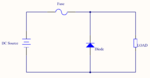
We wanted a reverse polarity protection for our ckt. We have below design.

Query.jpg

How much voltage drop we will get here?
Please suggest the D4 and Q68 for 16A load, lower drop in voltage is preferred.
Can you suggest any other ckt for better performance?
 

I presume that you want the "ext 24V" to travel through to the 24 V when its of the correct polarity?. The best way is with a 24V relay and a diode. You feed the output to the input via a pair of open circuit contacts. So the output is only there when the relay is energised. You feed the relay coil via the diode from the input so when the input is positive the relay pulls in and the + 24V appears at the output. You do not loose any voltage on the contacts and its capable of delivering many amps with the correct choice of relay.
Frank
 
This works well as long as the output (24VDC) is not supplied by another power supply (but if it is, I suppose this is the reason for the reverse protection being necessary? )

In that case, the relay would always stay switched on - no reverse protection.
 
Thanks chuckey, For suggestion. I will test the Relay option and present you the ckt.

erikl, No in this ckt we do not provide another source at output (24VDC), but the reverse protection is required because many time at the field, installation guy often makes mistake in wiring of +Ve and -Ve supply of 24VDC_Ext.
 

A large Schottky diode by itself will give you about a half volt drop in the forward direction. (What is the purpose of the transistor circuit after the diode)?

If you want less drop then that you could use a power MOSFET. A simulation of such a circuit is shown below.

Since a MOSFET conducts equally well in both directions, the P-MOSFET is shown connected with the input going to the drain so that it can block the reverse voltage when the drain becomes negative. For normal operation, when the drain goes positive, the MOSFET substrate diode initially conducts current and the output voltage starts to rise. When the voltage is high enough that the gate-source voltage exceeds the MOSFET threshold, it starts to turn on. With 24V applied, R1 and R3 reduce the gate voltage to 12V so it won't exceed the maximum Vgs rating of the MOSFET.

When the voltage is reversed, the MOSFET substrate diode is reversed biased and the MOSFET stays biased off (Vgs = 0V) thus the MOSFET blocks the reverse voltage as desired.

The MOSFET shown has an ON resistance of 3.6mΩ, giving a voltage drop of about 55mV @ 16A as shown by Cursor 1 in the simulation. You can use a different P-MOSFET as long as the current and voltage rating are greater than the input voltage, and the ON resistance gives you the desired maximum voltage drop when conducting the load current.

Note that if you can connect the circuit in the ground (negative) lead of the circuit being protected then you can use an N-MOSFET which, due to the higher N material mobility, allows the use of a smaller chip and cheaper device for the same current and ON-resistance rating.

Revers Protection.gif
 
Thank you crutschow for your valuable replay.

I just needed to check with my local supplier for this MOSFET, else is fine.

Note that if you can connect the circuit in the ground (negative) lead of the circuit being protected then you can use an N-MOSFET which, due to the higher N material mobility, allows the use of a smaller chip and cheaper device for the same current and ON-resistance rating.

No. We prefer to provide protection in Positive side only, because this GND(negative) is used as ref for external ckts.
 

Hi there,

We got reply for our suppliers, HAT1072H is not available.

We have following replacement suggested by suppliers, please comment on them:

1. ATP102 : -30V,-40A,18.5mOhm
2. **broken link removed** : -30V, -50A, 17mOhm
3. **broken link removed** : -30V, -38A, 17mOhm
4. AUIRF4905S : -55V, -42A, 20mOhm
 

Another one old method is there... Zero voltage drop, Very simple to design, Diode rating is low, not need for schottky diode... But again no protection for the reverse current flow(which is not important for your application), But every time you make the input as reverse, the fuse will blow & need to replace with a new one(I hope this will not happen very frequent). The circuit will remain safe because of the open circuit.

Regards
Udhay
 

Attachments

  • Capture.PNG
    Capture.PNG
    18.6 KB · Views: 103

Status
Not open for further replies.

Similar threads

Part and Inventory Search

Welcome to EDABoard.com

Sponsor

Back
Top