N
naeem.saleem.ns@gmail.com
Guest
I am currently working on a design that is based around LPC1759 microprocessor chip from NXP. Data sheet (pp-32&33) states that this IC has two independent power domains. IO pads are powered by (VDD(3V3) pins (pin21,42,56,77), while the VDD(REG)(3V3) pins (pin-34&67) power the on-chip regulator which in turn provides power to the CPU and most of the peripherals.
For this reason I design the circuit with split power supply. I have one circuit supplying to on-chip regulator (See the attached schematic called on-chip 3.3V supply)
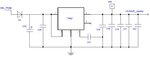
And another circuit supplying the IO pins and also back up battery voltage (See the attached schematic called IO 3.3V supply
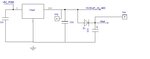
In the supply for on chip regulator, VReg1 is a 3.3V regulator from TI part no. TPS73033. Capacitor C25 is 1000uF to hold the charge for few milli-seconds after the input power is lost (detected on an interrupt line of microprocessor) so that processor could do necessary housekeeping before shutting down. This charge on C25 is protected from flowing back to rest of circuitry via diode D3.
The problem I have is related to this diode D3. I would like to use a Schottky diode here so that it has less voltage drop across it and C25 would be able to hold charge for longer duration across it i.e., for 5V input, 0.3V drop across D3, then voltage across C25 would be 4.7V. Compared to standard diode e.g., BAS16, that will have 0.7V drop hence 4.3V across C25.
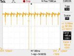
Initially I use a Schottky diode but it posed few problems. Diode I used is HSMS-2800-TR1G (Farnell part no: 1056832). When I power the circuit with 5V input I see loads of noise (spikes) on supply line after D3 and also at the output of LDO regulator (VReg1) (see the attachment called Noisy supply)
The frequency of this noise is 1kHz (approx.) and it causes the over all supply voltage to be much less than the required level. (I get 3.8V instead of 4.7V.
The further investigation revealed that by disconnecting the output of regulator from processor pins causes this noise to disappear so it is some how related to the load (i.e., processor). I tried to disconnect 1000uF cap from LDO’s input but no significant change on noise
I tried to connect a power inductor 220uH (Farnell Part No: 2286583) in series with LDO to the processor and it helped in reduction of the amplitude of this noise and also the over all current consumption on 5V line from 14mA down to 7mA. But the noise was still present
I replaced the Schottkey diode D3 with a standard diode BAS16, and all the noise disappeared (with 100uF back in circuit and no need for power inductor). This is peculiar as I cannot understand why replacing schotteky diode by a standard diode on power supply line would eliminate the noise when all it is doing is to act as a blocker for charge to flow in reverse direction in case of power failure.
Secondly, with standard diode in, when I program the processor using JTAG (Jlink from Segger), the voltage at the input of VReg1 (after D3) temporarily raises to 4.29V and when the code is running it comes down to 4.02V. So, its stays at 4.02V under normal operation but during the instance of programming, it is sitting at 4.29V. In both cases the output of LDO is 3.3V. (LDO is rated for upto 200mA current and the processor is hardly taking 20mA so we are well within the range of regulator's rating)
BOM: C26 is 220nF
C27 is 22nF
C28 is 2.2uF
C29, C30, C31 & C80 are combinations of 1uF and 100nF
For this reason I design the circuit with split power supply. I have one circuit supplying to on-chip regulator (See the attached schematic called on-chip 3.3V supply)
And another circuit supplying the IO pins and also back up battery voltage (See the attached schematic called IO 3.3V supply
In the supply for on chip regulator, VReg1 is a 3.3V regulator from TI part no. TPS73033. Capacitor C25 is 1000uF to hold the charge for few milli-seconds after the input power is lost (detected on an interrupt line of microprocessor) so that processor could do necessary housekeeping before shutting down. This charge on C25 is protected from flowing back to rest of circuitry via diode D3.
The problem I have is related to this diode D3. I would like to use a Schottky diode here so that it has less voltage drop across it and C25 would be able to hold charge for longer duration across it i.e., for 5V input, 0.3V drop across D3, then voltage across C25 would be 4.7V. Compared to standard diode e.g., BAS16, that will have 0.7V drop hence 4.3V across C25.
Initially I use a Schottky diode but it posed few problems. Diode I used is HSMS-2800-TR1G (Farnell part no: 1056832). When I power the circuit with 5V input I see loads of noise (spikes) on supply line after D3 and also at the output of LDO regulator (VReg1) (see the attachment called Noisy supply)
The frequency of this noise is 1kHz (approx.) and it causes the over all supply voltage to be much less than the required level. (I get 3.8V instead of 4.7V.
The further investigation revealed that by disconnecting the output of regulator from processor pins causes this noise to disappear so it is some how related to the load (i.e., processor). I tried to disconnect 1000uF cap from LDO’s input but no significant change on noise
I tried to connect a power inductor 220uH (Farnell Part No: 2286583) in series with LDO to the processor and it helped in reduction of the amplitude of this noise and also the over all current consumption on 5V line from 14mA down to 7mA. But the noise was still present
I replaced the Schottkey diode D3 with a standard diode BAS16, and all the noise disappeared (with 100uF back in circuit and no need for power inductor). This is peculiar as I cannot understand why replacing schotteky diode by a standard diode on power supply line would eliminate the noise when all it is doing is to act as a blocker for charge to flow in reverse direction in case of power failure.
Secondly, with standard diode in, when I program the processor using JTAG (Jlink from Segger), the voltage at the input of VReg1 (after D3) temporarily raises to 4.29V and when the code is running it comes down to 4.02V. So, its stays at 4.02V under normal operation but during the instance of programming, it is sitting at 4.29V. In both cases the output of LDO is 3.3V. (LDO is rated for upto 200mA current and the processor is hardly taking 20mA so we are well within the range of regulator's rating)
BOM: C26 is 220nF
C27 is 22nF
C28 is 2.2uF
C29, C30, C31 & C80 are combinations of 1uF and 100nF