Continue to Site

Welcome to EDAboard.com

Welcome to our site! EDAboard.com is an international Electronics Discussion Forum focused on EDA software, circuits, schematics, books, theory, papers, asic, pld, 8051, DSP, Network, RF, Analog Design, PCB, Service Manuals... and a whole lot more! To participate you need to register. Registration is free. Click here to register now.

[SOLVED] N Channel MOSFET switch's flyback body diode

Status
Not open for further replies.

JackofallTrades

Newbie level 6
Joined
Mar 28, 2014
Messages
11
Helped
0
Reputation
0
Reaction score
0
Trophy points
1
Activity points
103
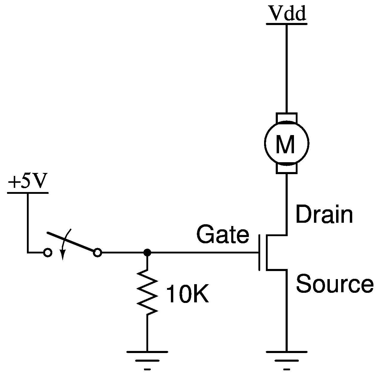
I have created a simple N-MOSFET switching circuit, as seen here, except I am driving a solenoid primary instead of a motor. (If important source voltage is 24V, coil resistance is 4ohms.)

fetswitch.jpg


Works great, and gives nice big EMF spikes. So, I placed a 1N4007 on the circuit as a flyback diode across the solenoid. Worked to very effectively eliminate the spikes but now the solenoid's response time is suffering.

A follow up question later will involve sizing a series resistor to speed this up, but looking at the circuit had me pondering something else.

The N-MOSFET has a body diode I have read repeatedly that can be used as a "freewheeling" or flyback diode. I do not understand how this works as the diode is directionally wrong to conduct the induced current.

My only guess is that if the induced current induces a voltage higher than the body diode's breakdown voltage, it will reverse conduct. Is this how the "body diode as flyback" idea works?
 

No, the body diode cannot be used as a free-wheel diode for the reasons you said. The way to protect the switch and still have decent solenoid performance is to put a Zener diode in series with a regular diode in parallel with the solenoid. The regular diode points up toward Vdd and the Zener diode points down toward the switch. Pick a Zener voltage value that is as high as possible without exceeding the voltage rating of the switch, minus Vdd. The higher Zener voltage you use the fast the solenoid will change. But the higher Zener voltage you use, the greater will be the stress on the switch. So use a switch with as high a voltage rating as you can get. That's how to get the best performance from your solenoid without blowing out MOSFETs.

You are right that putting a resistor in series with the solenoid will speed up the switching, but it will also reduce solenoid current. It is a bad deal, usually, to use a resistor to do that.
 
The "freewheeling" mode works for below-ground undershoots
but has nothing but avalanche breakdown, for positive ones
(like you'll get when you turn off the current path through the
solenoid).

Some FETs are "avalanche rated" and some are not. I do not
know how much avalanching even the "rated" ones can
take, reliably.

The drain-body diode will tend to have long storage times in a
high voltage FET, possibly longer than your cycle time in many
applications. If the body diode is still holding charge when the
drain goes high, say hello to Mr. Parasitic NPN in all of his
helpfulness. You generally do not want to use this "feature"
unless you know it very well and trust in manufacturing
consistency.
 

You can add a diode in series with the diode to speed up the operation of the solenoid but adding a zener as suggested by Tunnelabguy will give the fastest operation.
 

No, the body diode cannot be used as a free-wheel diode for the reasons you said. The way to protect the switch and still have decent solenoid performance is to put a Zener diode in series with a regular diode in parallel with the solenoid. The regular diode points up toward Vdd and the Zener diode points down toward the switch. Pick a Zener voltage value that is as high as possible without exceeding the voltage rating of the switch, minus Vdd. The higher Zener voltage you use the fast the solenoid will change. But the higher Zener voltage you use, the greater will be the stress on the switch. So use a switch with as high a voltage rating as you can get. That's how to get the best performance from your solenoid without blowing out MOSFETs.

You are right that putting a resistor in series with the solenoid will speed up the switching, but it will also reduce solenoid current. It is a bad deal, usually, to use a resistor to do that.

I don't get my electronics education from YouTube, but based on this would it be your opinion this video is all wet?

https://www.youtube.com/watch?v=KrJ3ZSI7T54

Granted, they have BJTs instead of FETs, but the idea of the flyback diode is the same, and I do not understand how there is an expectation of the middle circuit behaving any better than the left most.

Re: the series resistor, I should have been more clear. I would not place the resistor in series with the coil, I would place it in series with the flyback diode to dissipate energy during the time the diode conducts. Might I ask what advantage a series zener would have over a series resistor?
 

The body diode "can" act as a freewheeling diode if the mosfets are in the correct setup. For instance an H-bridge or half bridge arrangement. When driving an inductive load like a motor the "bottom" fets diode will circulate the current until the fet turns on.
In your case the body diode is doing nothing :0)
Neddie
 
I don't get my electronics education from YouTube, but based on this would it be your opinion this video is all wet?

https://www.youtube.com/watch?v=KrJ3ZSI7T54

Granted, they have BJTs instead of FETs, but the idea of the flyback diode is the same, and I do not understand how there is an expectation of the middle circuit behaving any better than the left most.
I agree. The diode in the middle circuit in that video is useless.
Re: the series resistor, I should have been more clear. I would not place the resistor in series with the coil, I would place it in series with the flyback diode to dissipate energy during the time the diode conducts. Might I ask what advantage a series zener would have over a series resistor?
A resistor in series with the flyback diode would be an improvement over no resistor because the coil current will drop faster. It is about half way as good as a Zener, and here is why. The thing you want to do is oppose the flow of current in the coil. When you do that, the coil reacts by raising the voltage on the switch. With a Zener, the voltage is allowed to rise as high as the switch can safely tolerate, and stay there until the job is done (the current drops to zero). With a resistor, the resistor produces more voltage at the beginning of the turn-off, and less voltage as the current decays according to an exponential L/R time constant. So the circuit is "trying harder" to at the beginning to oppose the current, and not so hard as the current decays. But the limit in both cases is the voltage that the switch can safely tolerate. With the Zener you are using that limit to its full all the time. With the resistor you are using that limit only at the very beginning. So on the average the circuit does not try as hard to stop the current with the resistor as it does with the Zener. It is a more effective use of the limited capabilities of the switch. However your resistor idea is so much better than the simple diode that you may not need the ultimate performance of the Zener. With the simple diode you are opposing the current with only 0.7 volts. Assume that the switch can handle 35 volts. With the proper sized resistor, the initial turnoff voltage at the switch will be 35 volts at the beginning, decaying to a mere 5 volts as the current drop to zero. Of the 35 volts, 30 volts will be directly opposing the current flow. That is 43 times better than opposing it with 0.7 volts, so the current will stop 43 times faster if you could maintain that 30 volts of opposition all the way to the end, which a Zener would do. But your resistor will start out opposing the current with 30 volts, and that voltage will drop to 0.7 volts over time. So I would guess that cuts the effectiveness roughly in half, when compared to the Zener. So overall the current will stop about 21 times faster with the diode and optimal resistor, as compared to the diode alone. So you have 1x with the diode, 21x with the diode plus resistor, and 43x with the diode and Zener.
 
Status
Not open for further replies.

Similar threads

Part and Inventory Search

Welcome to EDABoard.com

Sponsor

Back
Top