Continue to Site

Welcome to EDAboard.com

Welcome to our site! EDAboard.com is an international Electronics Discussion Forum focused on EDA software, circuits, schematics, books, theory, papers, asic, pld, 8051, DSP, Network, RF, Analog Design, PCB, Service Manuals... and a whole lot more! To participate you need to register. Registration is free. Click here to register now.

merging pwm and analog signal

Status
Not open for further replies.

doors666

Junior Member level 1
Joined
Mar 2, 2013
Messages
17
Helped
0
Reputation
0
Reaction score
0
Trophy points
1,281
Activity points
1,427
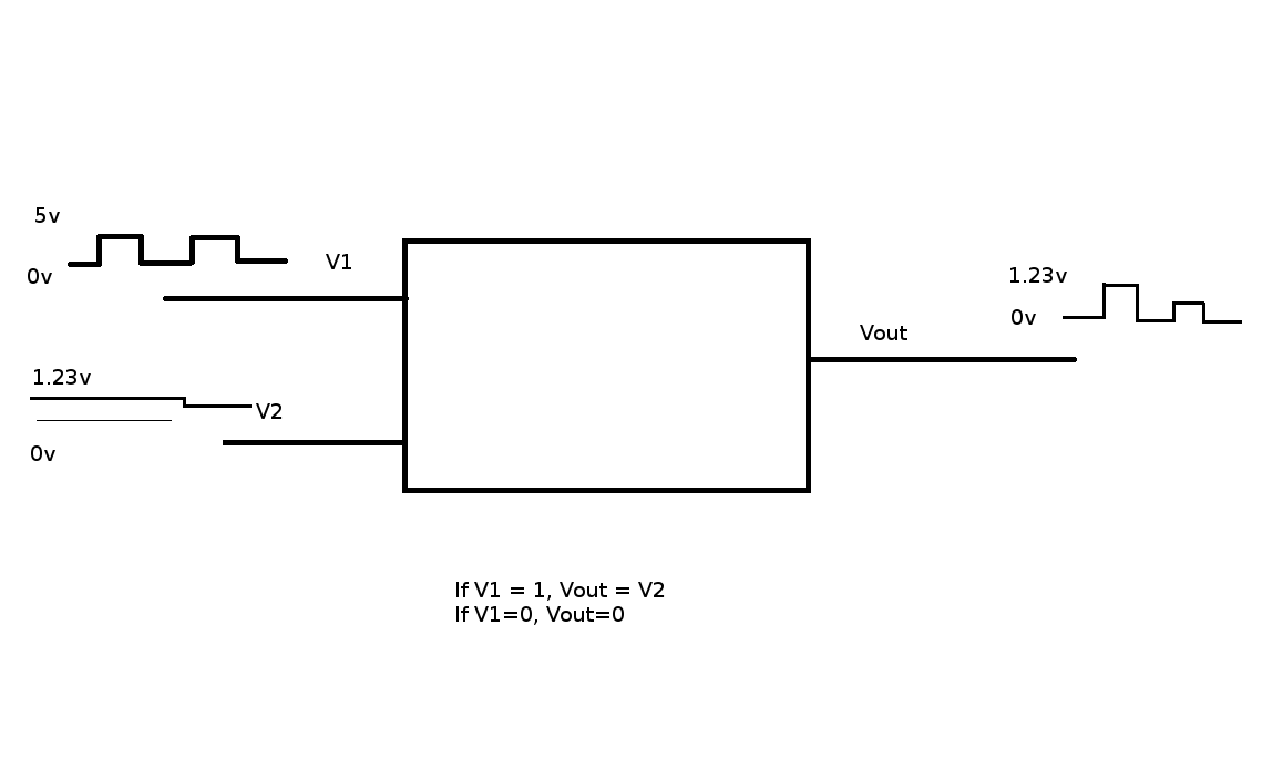
I have a analog dc signal for which the voltage varies from 0-1.23v. I also have a 3.3v pwm signal, for which the worst case frequency will be 1mhz. I need to merge these two so that the output signal is switched as per the pwm but the voltage level is as per the analog signal, kinda like a switched varying dc signal. Too much of voltage should not be dropped in the process and the fast response time is also important. How do I do this.
 

i have another question related to PWM so I guess i will add it here. How do I calculate the power requirements for components while using PWM.
e.g. if I use a 1 ohm current sense resistor for 5A current, I need a resistor of 25w + some margin. How much wattage resistor do I need if I am going to be doing PWM at lets say 10% duty cycle. Is it 2.5w and the same margin. Does the on time during pwm cycle play some role in this.
 

I do not understand your requirements. Are you saying you want to use the PWM (digital signal) to select one of two analog signals? I'm not sure what you mean by 'merge'.

In theory the average power dissipated in your resistor is the conventional V*I with the result multiplied by the PWM ratio so your 2.5W calculation is correct. However the component must also be able to withstand the pulsed heating at full power. If it is a wirewound resistor with considerable body mass you should be OK to use one with proportional rating but some smaller components may fail due to thermal shock. You should also bear in mind that in the event of circuit failure or the PWM being at low frequency, the resistor may be called upon to dissipate full power. Personally, I would reconsider using 1 Ohm in a 5A sense application and use a lower value with an amplifier after it. At 5A it will drop 5V, if you use say 0.1 Ohms instead it will only drop 0.5V and dissipate only 2.5W.

Brian.
 

Generally speaking, a SPDT analog switch can do what you apparently want. Nothing has been said about voltage source and load impedance. You may want to use buffer amplifiers.
 

ya you can do as fvm said. for power calculations the resistor you choose shd withstand the maximum current, If the power description is more make some cooling arrangements better choose a low resistor value or a hall effect current sensor..
 

I wonder if doors666 means they want the PWM to carry one analog signal, according to its ratio but the amplitude of the PWM signal itself to carry the other analog signal. If that is the case, yes it is possible but they would have to use a sample-and-hold circuit triggered by the rising edge of the PWM signal to extract the 'real' analog signal and a comparator to slice the PWM at low level to extract the 'digital' analog signal. Both signals would have limited amplitude range as it would fail to work if eiher the PWM pulse level was too low or the pulse width was too narrow.

Brian.
 

I guess an image will clarify what i want.


Thanks, that clarifies it.

The scenario is as I described in post #6. At the sending end you need to use an analog switch to 'chop' the signal under control of the PWM. At the receiving end you need to sample the amplitude immediately after the rising edge of the PWM signal and hold it's level until re-sampling at the next rising edge. That will restore the analog (V2) signal as best as is possible. What you can't do is use very short PWM pulses because it wont allow the sample and hold circuit enough time to snapshot the voltage and you can't use very low analog voltage because it will make it impossible to recover the PWM waveform.

Brian.
 

It hasn't been said that the PWM signal shall be recovered, in so far I would take the specification as is, just an ideal digital modulator which can be well achieved with an analog switch.

Of course you can ask about the purpose of this signal and if the OP has considered it's application well. But to me, the specification sounds plausible enough.
 

Basically I want to control a mosfet with this signal. I want the analog signal to control the current level and pwm for controlling the switching at the same time. Current capability might not be there so i will need to use a mosfet driver or something like that.
 

I'm not clear on this - what is the purpose of the PWM? Are you trying to 'merge' the two signals so they can both be recovered again or are you simply trying to chop the analog signal up? If you amplitude modulate the digital PWM levels and set the amplitude to zero there will be no PWM anyway, it will switch between digital zero and analog zero so nothing will be produced.

Brian.
 
  • Like
Reactions: FvM

    FvM

    Points: 2
    Helpful Answer Positive Rating
According to block diagram PWM pulses are used to control the switch while analog DC determines the amplitude of PWM pulses on output.
 

Hi by doing PWM itself you can control the average current and power Is ther anything special need about Changing the Amplitude???

Try to explain your application.. If its just a power control then PWM is enough..
 

How do I feed this signal to a mosfet? My switching speed can be as much as 1mhz and I dont have enough current in this signal for fast switching. I looked at quite a few mosfet driver chips, but most of them are suitable for dc-dc converters or for h-bridges. I found a few simple ones but those dont handle analog signals. I tried making a totem pole drivers using bd139/bd140, but looks like those transistors can also take input currents of some 1A and the datasheets arent very helpful as a lot of information is missing. Could someone please advise me on either some simple mosfet driver chip that can add current to an analog signal or some transistor that I can use that will give me enough current gain with good speed with a totem pole driver.
 

Take a step back. It still isn't at all clear what you are trying to achieve. We can see you want to send two signals as one but the limitations of doing that are nothing at all to do with totem pole drivers or current limitation. The data sheets are quite comprehensive. Please explain what you mean by "those transistors can also take input currents of some 1A", many transistors can if you push them hard enough but that isn't normally what we would do with them.

Brian.
 

Lets say system is designed for max 5A. The user should be able to configure it like this -

Run the system at 2A, with 10% duty cycle at 10khz.

Microcontroller's dac will give me a voltage representing the 2A on a 5A scale. UC will also give me the pwm signal. Now the mosfet should drive the load at 2A, and switching it on and off using the given PWM signal. It should be real pwm, not like run it with averaged out continuous current.

I need to handle upto 500khz, so the gate capacitance needs to charge and needs high current or response time is slow. I used bd139/140 for this (totem pole), which has max collector current at 1.5a and max base current at 0.5a, so not much of gain, looks like I need to find out a transistor that has more gain. looking into it.
 

It's starting to get clearer.

Firstly, you must understand that it is technicaly impossible to achieve what you want. Chopping 0V with a PWM driven switch will give contant zero SIGNAL out, in other words no analog and no PWM whatsoever. Nothing can be recovered by your driver circuit.

Lets assume you limit your analog voltage so it never drops below 0.5V. Your PWM signal will then go between 0V (PWM off period) and 0.5V (PWM on period). To drive your load you need to recover the PWM waveform before using it. The voltage is already below that needed to turn any transistor on and off so you need to convert it to a more usable level first. As the waveform is small and likely to be distorted I would suggest you use a comparator for that. Set it's threshold at about half the lowest analog voltage you will carry, in this example at 0.25V. You now have recovered the PWM waveform and can use a suitable current driver to feed the MOSFET gate.

Now you have to recover the analog voltage. If the PWM ratio is 0% (always off) there will be no analog voltage so there would be no point in attempting recovery, so in the same way you have to limit the lower analog voltage, you also have to limit the lower PWM duty cycle. At 1MHz PWM rate, and say 1% duty cycle you still only have 1 cycle at 10MHz to measure the amplitude. This is too fast for a normal DAC to measure so you will be forced to use a buffer amplifier then sample and hold (S&H) circuit. You have a reference point to gate the sampling point at the leading edge of the PWM signal, in fact it's the only point you can be sure the analog signal is there at all. The hold circuit will maintain the voltage throughout the remainder of the PWM cycle until you can take the next sample and give time for your ADC or driver circuit to use it.

May I ask what the load is in this application. It seems counter-intuitive to use PWM to control something and at the same time limit it's power source compliance.

Brian.
 

It's a bit confusing that you started the thread with a switched voltage signal and ended up with a current source. It would be helpful to have an unequivocal signal specification as a first step.
 

To say easily Try to follow a chopper circuit with a PNP constant current source..
use a MOSFET for chopper and BJT for CC source. select both transistors more than 5A.

and you may also drive like this
https://www.daycounter.com/Circuits/Current-Servo/Current-Servo.phtml
Voltage controlled Current source, you can use the DAC output to match with the current source.
Current-Servo.gif
 

To say easily Try to follow a chopper circuit with a PNP constant current source..
use a MOSFET for chopper and BJT for CC source. select both transistors more than 5A.

At low switching speeds, the sketched setup can work with certain accuracy. At several 100 kHz or 1 MHz, unwanted circuit effects are tending to dwart any reasonable specification. We didn't hear the specification yet, but I guess you need to refer to alternative circuit topologies, either current switches or wideband current drivers.
 

Status
Not open for further replies.

Similar threads

Part and Inventory Search

Welcome to EDABoard.com

Sponsor

Back
Top