Continue to Site

Welcome to EDAboard.com

Welcome to our site! EDAboard.com is an international Electronics Discussion Forum focused on EDA software, circuits, schematics, books, theory, papers, asic, pld, 8051, DSP, Network, RF, Analog Design, PCB, Service Manuals... and a whole lot more! To participate you need to register. Registration is free. Click here to register now.

23cm filter using smd inductors

Status
Not open for further replies.

neazoi

Advanced Member level 6
Joined
Jan 5, 2008
Messages
4,123
Helped
13
Reputation
26
Reaction score
15
Trophy points
1,318
Location
Greece
Activity points
36,955
Hello,
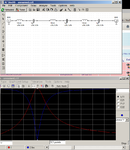
I have designed a simple LC series filter using smd inductors for the 1296MHz.
The picture shows 3 such filters cascaded.
When two or more simple series LC filters are cascaded the filter response is better.
Since it is desirable to have equal inductors in the filter, do you think the filter I designed would be ok?
 

Attachments

  • f.png
    f.png
    54.5 KB · Views: 117

You filter will be very sensitive against to component tolerances because you used large inductor values with small capacitor values to satisfy the wanted rejection.
If you do a sensitivity analysis, you will absolutely see what I mean.
Why don't use consider standard filter approximations like Butterworth or Chebychev ??

I did so with rfsim99. But the capacitances where of the order of femptofarad, which cannot be made. Also the coils were unequal which adds cost (need to obtain more values)
 

I have studied a little bit on your cascaded filter.
I have given 10% tolerance to the inductors and capacitors.And also I have added 0.2 Ohm to each inductor.( More or less practical values )
Look at the insertion loss probability of your filter with these tolerances.Insertion loss -8.1dB with 41% probability.It's huge..isn't it ??
Insertion loss without tolerances is less than 0.1dB ..

Distribution.png
 

I have studied a little bit on your cascaded filter.
I have given 10% tolerance to the inductors and capacitors.And also I have added 0.2 Ohm to each inductor.( More or less practical values )
Look at the insertion loss probability of your filter with these tolerances.Insertion loss -8.1dB with 41% probability.It's huge..isn't it ??
Insertion loss without tolerances is less than 0.1dB ..

View attachment 103287

Thank you bigboss!
The purpose is to use the filter after a combo generator to keep close to the band frequencies, whereas reject out of band (far away) frequencies. I would like to do it using non pcb printed components but I cannot find less than 1pf capacitors, so the lower capacitance limit is 1pf. I have found some 0.1% 1pf capacitors and some 2% 15nH inductors.
Is the frequency at the top of the filter is not a big issue (as in my case) would that type of filter be suitable?

I welcome any suggestions about other topologies but with 1pf min caps
 

What is your required bandwidth? If you relax the BW of the filter then you can gain tolerance to component variation, and better IL.
 

What is your required bandwidth? If you relax the BW of the filter then you can gain tolerance to component variation, and better IL.
I believe 100MHz or so at 3db would be a relatively logically filter
 

Thank you bigboss!
The purpose is to use the filter after a combo generator to keep close to the band frequencies, whereas reject out of band (far away) frequencies. I would like to do it using non pcb printed components but I cannot find less than 1pf capacitors, so the lower capacitance limit is 1pf. I have found some 0.1% 1pf capacitors and some 2% 15nH inductors.
Is the frequency at the top of the filter is not a big issue (as in my case) would that type of filter be suitable?

I welcome any suggestions about other but with 1pf min caps
A better solution is to realize this filter by MS technique at that frequency on a cheap double sided FR4 substrate.
It will be more robust and consistent.
 

The so called "cascaded" filter still isn't better than a single LC filter with 3 L and 1/3 C.

It's true that LC bandpass filters in standard topology might involve extreme component values, but there are alternative topologies like "coupled resonator" that overcome the problem.
 

A standard MS Interdigital filter may serve your goal.It's based on a standard 1.57mm FR4 substrate with 35um copper clad.Input and output impedances are 50 Ohm.
Resonance capacitors are GRM1555 series of Murata 1.5pF.Here a EM simulation result is given, the exact response will be more or less same or better.(maybe worse, who knows ??)
Return Loss and Insertion Loss are a little bit our of spec due to substrate losses and low frequency but it's not so bad at all..
Physical Filter.pngFilter Response.png
 

Another implementation on a Rogers 4003C,0.5mm height with standard 35um copper clad substrate.
1296MHZ_BP_Filter.png1296MHZ_Close_In_S21.png1296MHZ_Close_In_S11.png


A SMD LC filter is fine for the low GHz range, if you made a design with feasible component values and have the capabilities to tune it by changing components interactively under VNA control. You'll use components with sufficient Q and high SRF, e.g. wire wound 0402 inductors and microwave ceramic capacitors.
 

Thank you for your replies. I see a tendency towards microstrip filters and indeed these are better (but creater physical size).
So to conclude an SMD based filter is out of the question?
We have to talk about the practice..
I gave you a simple tolerance analysis above.But if you able to get precise trimmer capacitors and inductors with tight tolerance, it's possible to realize this filter by tuning.
But I assure you that the filter will have a quite rough response if you accept that.
The response is not too much of a problem, is it does not introduce too much loss, since it will be used after a harmonics generator to roughly select the band of interest.
I am thinking of trarting with a 2% chip inductor and a 0.1% capacitor. Is response is affected too much I may connect in parallel/series a precision trimmer to tune the filter.
I will first start with one pole series and then cascade.
How does it sound?
OK, I understood..
In this case-perhaps- you can design a Low Pass-High Pass combination in cascade.I will check that for you..
 
  • Like
Reactions: neazoi

    neazoi

    Points: 2
    Helpful Answer Positive Rating
A practical feasible filter with standard Murata components.I hope it's good for you..
1296BP.png1296MHz_BP_ILRL.png
 
  • Like
Reactions: neazoi

    neazoi

    Points: 2
    Helpful Answer Positive Rating
A better solution is to realize this filter by MS technique at that frequency on a cheap double sided FR4 substrate.
It will be more robust and consistent.

Related to this question, I ask about using interdigital technique when the purpose is harmonic filtering because I suspect that some filters will respond again in periodic fashion far away from the passband.

I have encountered a S-Band diplexer filter, constructed as metal posts with tuning screws above, intended to pass part of the band while providing large rejection to another part. It seemingly allows 4th harmonic through which then causes interference in X-Band.

Can interdigital filters be made so that the out-of-band attenuation simply gets greater for frequencies that are higher?
 

Thank you very much for your time!
Could you upload a larger picture of the schematic?
Click the picture, it will be expanded.Then click again, it will be full screen.Click once more to zoom-in...
It's sufficiently large.
 
  • Like
Reactions: neazoi

    neazoi

    Points: 2
    Helpful Answer Positive Rating
Status
Not open for further replies.

Similar threads

Part and Inventory Search

Welcome to EDABoard.com

Sponsor

Back
Top