Continue to Site

Welcome to EDAboard.com

Welcome to our site! EDAboard.com is an international Electronics Discussion Forum focused on EDA software, circuits, schematics, books, theory, papers, asic, pld, 8051, DSP, Network, RF, Analog Design, PCB, Service Manuals... and a whole lot more! To participate you need to register. Registration is free. Click here to register now.

snubber across relay ? solution for damage relay

Status
Not open for further replies.

Electro nS

Full Member level 6
Joined
Mar 9, 2013
Messages
324
Helped
49
Reputation
98
Reaction score
48
Trophy points
1,308
Activity points
3,818
dear guys i am running BIG DC motor from a relay

the relay is acting weirdly after some uses , it gets stuck and needs to be switched on and off several times to run again . some times i hit the relay in order to work !! i have 2 theories for this problem : 1- relay is bad quality (chinease ) and is losing most of its life while soldering it at high temperature to the PCB !
2- the spikes from inductive load are killing it

please advise from your knowledge and experience which is the most likely to happen ?
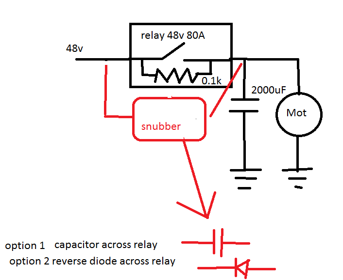
i attached a block diagram of the circuit , i have capacitor across the motor and i am using a 100ohm resistor across the relay to precharge the bulk capacitor before turning on the system !
the block in the red is my thoughts of solution for the problem , A capacitor or a reverse diode across the relay contact .
Note : the relay coil (0.1A) (is being switched by npn darlington from uC and is well protected )


You should have an idea about the actual motor current, both steady-state and inrush, to determine if the relay is capable to switch it frequently. If not, you don't need to worry about spikes because switching the motor a few times might kill the relay anyway.

The capacitor causes a large inrush current and will make things worse, the 100 ohm ersistor has no effect at all. A free wheeling diode is the right contact protection. Something like a 3 or 5A rectifier diode should be fine.
 
the stall current of the motor is around 80A , and continous is in the range of 20A , the relay is automotive (should be of that grade ) it is one of those plugable and used for "march" (starter of a car) . (the rating is as follows : 24v for the coil , the contact is rated 14v/80A . i am giving the coil 24v , but i am using 36-48v on the contact maybe this is causing problems ??? )
check this link : **broken link removed**

and yes i know the capacitor has great inrush current , why precharging with 100ohm is not enough 48/100=2A is this big amount ?? the datasheet says its ripple current is 2.2A , if not suggest how much should i limit the inrush current ( for example 1k gives 200mA is this good ??? )
 
Last edited:

Someone isn't looking at the schematic or using Ohms Law properly! The capacitor is across the motor so is shunted with approximately 0.6 Ohms of motor resistance (based on 48V and the quoted stall current). The 100 Ohm resistor will only pass 48/100 = 0.477A and charge it to only 0.28V !

Brian.
 
No precharging will happen in your circuit (respectively only if you disconnect the motor).

the stall current of the motor is around 80A , and continous is in the range of 20A , the relay is automotive (should be of that grade ) it is one of those plugable and used for "march" (starter of a car) . (the rating is as follows : 24v for the coil , the contact is rated 14v/80A . i am giving the coil 24v , but i am using 36-48v on the contact maybe this is causing problems ??? )

The relay isn't specfied for 48V, so can just guess if and how much the switching current must be reduced. On the other hand you'll hardly find small relays with similar current rating other than automotive types. I would try if you get suffcient lifetime with a free-wheeling diode.

The diode must be connected across the motor rather than the relay contact.
 
No precharging will happen in your circuit (respectively only if you disconnect the motor).

The diode must be connected across the motor rather than the relay contact.

so if i disconnect the motor , the precharging is good or should i increase R ?

- - - Updated - - -

Someone isn't looking at the schematic or using Ohms Law properly! The capacitor is across the motor so is shunted with approximately 0.6 Ohms of motor resistance (based on 48V and the quoted stall current). The 100 Ohm resistor will only pass 48/100 = 0.477A and charge it to only 0.28V !

Brian.

LOL , you are right , but if no motor is there , the circuit is acceptable ? or do u have an advise on this ??

- - - Updated - - -

No precharging will happen in your circuit (respectively only if you disconnect the motor).


On the other hand you'll hardly find small relays with similar current rating other than automotive types.

yes u are right but do you know why ?? i have searched alot , i have found only bulky and pricy relays , let alone solid state DC relays are crazly priced !! but WHY ??
 

LOL , you are right , but if no motor is there , the circuit is acceptable ? or do u have an advise on this ??
If the motor is removed what point is there in having the rest of the circuit?

I think the first thing you should consider is whether it is acceptable to apply full voltage to the motor immediately or whether it should be stepped up as the motor gathers speed so that the current is kept at a manageable level. Don't forget that in your present circuit, at the moment of switch on, not only does the capacitor take a surge to charge it but the motor is effectively stalled so the initial current will be much higher than the normal running current.

I am not sure what kind of motor it is or what load it is driving but I would consider using two or more relays, each bypassing a low value resistor (say 0.5 Ohms). When switched on you have two resistors in series to limit the current then after a brief period you short out the first then the second with relay contacts. That keeps the current down low enough that a standard automotive relay should work and it also limits the power on surge. I would also forget the capacitor unless its needed for some other purpose but add the diode across the motor.

Brian.
 
If the motor is removed what point is there in having the rest of the circuit?

Brian.
what i meant is that , regardless of the motor , lets say in another circuit i am using a similar capacitor , is this considered precharging , or should i use different R value to precharge this size of capacitor ??


for the rest of the suggestion , i think it is very realistic , although the current in those resistors will produce a problem of overheating resistors , i will study that and see how it will be later .
the best might be to use single mosfet or (h-bridge) to soft start and control speed as well . but in this case the capacitor is staying and the relay (for bi-passing precharge resistor )
 

you are right , but if no motor is there , the circuit is acceptable ? or do u have an advise on this ??
Acceptable for what? Switching no motor? I think, the circuit is just good for nothing.

There's a high volume demand for automotive relays, so they are quite cheap. But no similar demand for high current 48 or 60 V DC relays. DC relays are designed to safely switch-off a certain amount of inductive load, which requires an increasing effort for higher voltages.
 
what i meant is that , regardless of the motor , lets say in another circuit i am using a similar capacitor , is this considered precharging , or should i use different R value to precharge this size of capacitor ??

It is acceptable to use that kind of circuit to precharge a capacitor but I can't see why you would want to do that. Normally the capacitor would have other components connected across it (like the motor in your schematic) so they would consume the pre-charging current and result in a lower voltage. It isn't clear to me why you added that capacitor across the motor anyway, it doesn't really do anything, can you explain please.

Brian.
 
Status
Not open for further replies.

Similar threads

Part and Inventory Search

Welcome to EDABoard.com

Sponsor

Back
Top