tanzil_dhk
Advanced Member level 4
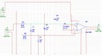
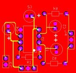
I fabricated a PCB board first time and used trace width of 20 mil for power traces and 10 mil for all others. When i check the circuit with dc input voltage (ex:50 mv- 600 mv) everything is perfect.
When i connect it to a real input (also a dc potential in the same range, ~30 uA current), the circuit receive signal much lower than original.Other parts of the circuit are working fine, just i am receving very low signal as soon as it is connected to circuit input.
Can it be due to the trace width. Or if you have any other idea or suggession please help.
NB: A little more about my circuit, the input pass through RC filter and then amplifier. The filter has nothing to do with the low signal, since i am getting the low signal even before filter. I had already been using same circuit with sholdering on veroboard, so the problem is not related to circuit design, i think .