Continue to Site

Welcome to EDAboard.com

Welcome to our site! EDAboard.com is an international Electronics Discussion Forum focused on EDA software, circuits, schematics, books, theory, papers, asic, pld, 8051, DSP, Network, RF, Analog Design, PCB, Service Manuals... and a whole lot more! To participate you need to register. Registration is free. Click here to register now.

PIC 16f877a/ 18f4550 trainer

Status
Not open for further replies.

easy electronics

Member level 3
Joined
Mar 3, 2014
Messages
63
Helped
0
Reputation
0
Reaction score
0
Trophy points
6
Activity points
485
Hi ,
i want to make a trainer board for pic 16f877A or 18F4550 .
i use PROTEUS ARES for pcb designing .
can someone give me its design or any kind of help.
 

One the best, but often overlooked, reference design resources is the manufacturer of the microcontroller.

Microchip offers several development boards, complete with schematics and BOM for both those particular microcontrollers.

Three of the most popular are:

PICDEM 2 Plus

PICDEM FS USB

PIC18 Explorer Board

BigDog
 

Hi,

You might find chips like the 18F4520 , 4620 or 45/46k20/22 are the more direct equivalents of the 16F877a.

The 4550 has all the complex USB functions which can be a pain to use when doing more basic circuits/programs.

What programmer are you intending to use ?
 

Dear wp100 i want to make my own training board (development board).
i have pickit2 for programming.
 

Dear wp100 i want to make my own training board (development board).
i have pickit2 for programming.

Hi,

Ok you have a great programmer /debugger with the Pk2.

Making a dev board is so much down to you and what you want from a board.

You will probably have looked at some of the commerical ones like MikroE but do you really want dozens of switches and leds ..

What you will find is that as your experience grows so will the needs of your dev board.

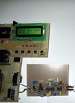
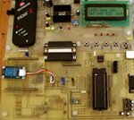
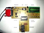
I've probably made 3 or 4 over the years and find this one probably the most versatile.

Its a two part board, joined like the Eblock boards. http://www.matrixmultimedia.com/eblocks.php
The main board contains the basics that are common to every project, programmer, power supply, basic switches, leds and display.

To that I connect a project board, say one for a small pic and one for a 877a/4520 board.
You can then just plug your project board in and out without having to change every thing if you were using just one big board.

Some pics of my diy ones below.

As said, every ones needs are different, so just write down your needs and design from that.
 

Attachments

  • dev.jpg
    dev.jpg
    79.5 KB · Views: 40
  • 2008-06-30 013.jpg
    2008-06-30 013.jpg
    60.4 KB · Views: 48
  • 2010-06-19 001.jpg
    2010-06-19 001.jpg
    73.1 KB · Views: 45

hi
Thank you sir wp100 for your reply. i want to make training board for students.
i want to make like this oneDD-DK16f877_2.PNGDD-DK16f877_1.PNG
 

i have found only circuit diagram not pcb designe.
i want pcb designe if possible.
 

i have found only circuit diagram not pcb designe.
i want pcb designe if possible.


Hi,

Even if you could copy that design, its a multi layered board which you would have to have manufactured for you.

Probably cheaper to buy the complete ready made trainer board.

You could do your own pcb design as a single sided board though that would need lots pcb links.
 

First try to design a small design like led blinking design

Then improve to seven segment
Then LCD / RTC
Then USART / Temp

Finally you will have good feature Reich development board with much experience

Sprint layout 5 also good design software as well as portable

https://www.abacom-online.de/uk/html/sprint-layout.html
 

i have found a beautiful board .and i would like to share these with all of you.
trainer2.jpgtrainer2.jpg
proteus layout file
orignal source is here
 

Attachments

  • trainer.rar
    19.8 KB · Views: 45

Hi,

Looks like a good find with everything on a single sided pcb that has good thick tracks so should be easy to make your own.:smile:

If you make the 4550 board, if you insert a jumper on pin18 to isolate the USB capactitor you can then use the easier to program 18F4520 and the 16F877A chip as well.

Being so modular you can add in the surrounding hardware devices when you are ready rather than populating them all at once.

I would also try an fit a 6 pin connector so you can plug the Pk2 straight in to the board, at the moment seems you would have to use jumper wires to connect one or keep removing the chip to a programmer board which is not a good way.
 
Last edited:

Status
Not open for further replies.

Similar threads

Part and Inventory Search

Welcome to EDABoard.com

Sponsor

Back
Top