Continue to Site

Welcome to EDAboard.com

Welcome to our site! EDAboard.com is an international Electronics Discussion Forum focused on EDA software, circuits, schematics, books, theory, papers, asic, pld, 8051, DSP, Network, RF, Analog Design, PCB, Service Manuals... and a whole lot more! To participate you need to register. Registration is free. Click here to register now.

[PIC] Help with Fluorescent Lamp ON/OFF control using PIC Microcontroller Board

Status
Not open for further replies.

richardlaishram

Member level 4
Joined
Jan 6, 2013
Messages
77
Helped
6
Reputation
12
Reaction score
6
Trophy points
1,298
Location
Planet Earth
Activity points
1,804
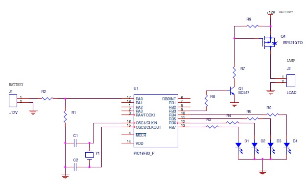
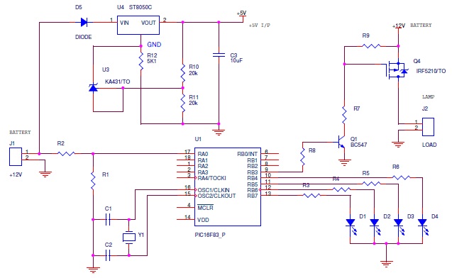
I've designed a PIC16F716 Microcontroller Board which detects battery voltage (12V Battery) using ADC and turns off the load when battery voltage is low (11V). Also 4 LEDs indicates the battery level. The board works perfectly with 12V bulbs and LED panels.
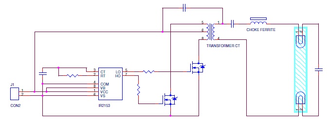
But when a 12 fluorescent lamp driver circuit is connected at the load the battery level indicator flickers fast and the load is turned ON/OFF at times even if the battery level is 13V approx.
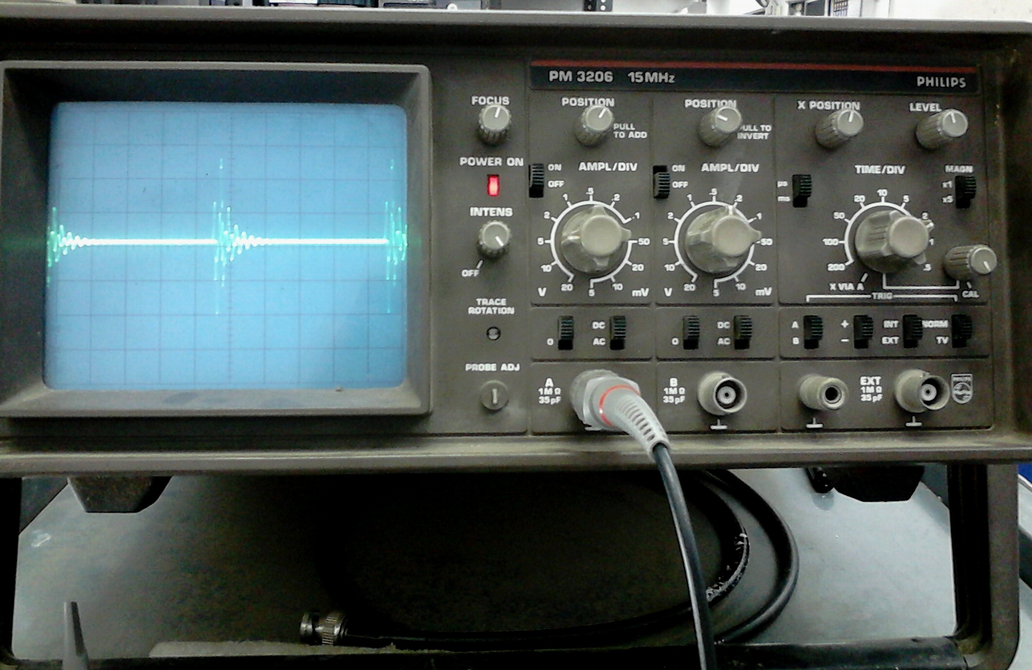
I'm doubting a noise from the lamp which operates at a very fast frequency (40KHz approx.). I've Googled about harmonics and all related information but I'm still helpless.

Please guide me how to avoid this or suggest any filter circuit to avoid the noise.
 

Fluorescent lamp uses inductor choke or electronic choke? If inductor type then your MCU needs EMI shielding.
 

A 12V to high voltage inverter is likely to cause considerable interference on the supply line and I suspect your ADC is reading that and getting wrong information about the state of the battery. When it decides to turn the lamp off, the interference is removed and the lamp tries to turn on again, it gets into an oscillating circle.

First, confirm this by connecting a capacitor across the input of the ADC pin to ground (try 1uF) and see if it changes or stops the flicker. If it does, you need to consider a design change to prevent anything above very low frequency reaching the ADC pin.

Brian.
 

Fluorescent lamp uses inductor choke or electronic choke? If inductor type then your MCU needs EMI shielding.
It's an electronic choke and I guess the circuit will be something like this.
7434524900_1393845481.jpg


Any suggestion on EMI shielding? I checked with an Oscilloscope and the DC input is showing some noise instead of the straight line DC, hence the problem.

- - - Updated - - -

First, confirm this by connecting a capacitor across the input of the ADC pin to ground (try 1uF) and see if it changes or stops the flicker. If it does, you need to consider a design change to prevent anything above very low frequency reaching the ADC pin.
I tried with the 1uF electrolytic capacitance but the problem still exists. Is there any way to avoid this noise, I'm not so sure what you meant by design change. Can you please explain me in brief?
 

Is there opto isolator between MCU and relay? If not add it.
 

Is there opto isolator between MCU and relay? If not add it.
First of all I'm not using a relay, I'm using a transistor MOSFET pair to directly drive the load, since the load is DC. The problem with using an opto is that I'm using the same battery for powering up the MCU board and driving the load. Also I'm sensing the Battery level with an ADC. So I don't think it's going to help if I use an opto in this circuit, please enlighten me.
 

Sorry for the delay. I don't have the proper schematics, so I've drawn one. I missed out few common pins which is not necessary.
6360973700_1393855945.jpg

On the load side, I've to connect the Lamp circuit I've posted above.
 

Attachments

  • Board.jpg
    Board.jpg
    38.9 KB · Views: 60

Should work. I would add a 100nF capacitor across R1 to filter noise on the supply line and also add a capacitor of say 1000uF across J2 (the lamp circuit). The lamp inverter relies on the low impedance of the battery to work properly, it's quite likely the extra few Ohms across Q4 is enough to stop the inverter running smoothly.

Brian.
 

Capacitors are not helping in any way :sad:
I'm getting a similar kind of spikes at the ground every few micro-seconds when I checked with an oscilloscope.
6589789800_1393924130.gif


The ground itself is not a straight line when load is connected. The same spike is visible with the ADC pin and everywhere.
 

I still think it's power related. Because of the high current spikes, you need to be very careful about the grounding. Ideally you should have a voltage regulator (78L05 or similar) to power the PIC and all the grounds should connect to one physical spot, including the regulator and its associated capacitors. I think it's the voltage drop in the resistance and inductance of the wiring that is causing your problem.

You can't avoid the spikes but you can stop them appearing across sensitive points in the circuit.

Brian.
 

I've added the power supply circuit in the previous schematics. The reason for not using 7805 is to make the circuit work in lower voltage also (~5V)
6982606600_1393929219.jpg


The spike I've attached above is only for representation. When I connect the probe's ground, spike is seen (voltage spikes on ground itself, not current).
 

Put a 104 capacitor directly between the power pins of the PIC, on the track side of the pcb.
 

Put a 104 capacitor directly between the power pins of the PIC, on the track side of the pcb.
Tried that, it's not helping with the spikes in the ground level.

I'm attaching the image from the probe also in case that might help.
2207549900_1393933042.jpg
 

Problem is due to physical layout. Make ground connection of FET from near the supply. Post some pics of wiring and front and back of board.

Pulses on scope can also be picked from air if probes are not rightly connected.
 

Status
Not open for further replies.

Part and Inventory Search

Welcome to EDABoard.com

Sponsor

Back
Top