Continue to Site

Welcome to EDAboard.com

Welcome to our site! EDAboard.com is an international Electronics Discussion Forum focused on EDA software, circuits, schematics, books, theory, papers, asic, pld, 8051, DSP, Network, RF, Analog Design, PCB, Service Manuals... and a whole lot more! To participate you need to register. Registration is free. Click here to register now.

I2C and pins: noob questions

Status
Not open for further replies.

benjamin42

Newbie level 3
Joined
Feb 26, 2014
Messages
3
Helped
0
Reputation
0
Reaction score
0
Trophy points
1
Activity points
22
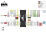
On the following image, we can see an MPU-9150 from Invensense being interfaced with an Arduino.

**broken link removed**

I want to interface it with an interface board for the TinyDuino:

**broken link removed**

I do not understand why the SDA/SDL connectors are linked to A2 and A3 pins, is this mandatory and arbitrary? Can I change it to any other pin? Behind the scene I use an I2C library (Wire) to communicate with the device, so I would just need to make sure the connections are well made.

Also, is it a good idea to glue the other sensor board on the Proto board?

Thank you very much
 

The SCL/SDA pins are actually pins A5 and A4 and not A2/A3, you can see the pin names printed on the back side of the board.

The location of these pins can't be changes because that it the location where the mcu output the I2C peripheral, the only alternative is to use a software I2C if you want.
 

Attachments

  • atmega328w.png
    atmega328w.png
    331.1 KB · Views: 59

The SCL/SDA pins are actually pins A5 and A4 and not A2/A3, you can see the pin names printed on the back side of the board.

The location of these pins can't be changed because that it the location where the mcu output the I2C peripheral, the only alternative is to use a software I2C if you want.


1) Thanks for pointing out the actual pins
2) Is this a rule? Always use A4/A5? Where is this supposed to be documented? SEE EDIT
3) I am actually using I2C software, where the software simply access an I2C address (Wire.beginTransmission(I2C_ADDRESS)). Does this mean I can use any pin?

Thanks.

EDIT: Thanks for the diagram, I see now why it needs to be A4/A5.
 

I'm not sure if the SCL/SDA are always located in pins A5 and A4 in all arduino but at least for the board you show they are.

The board uses either an mega168 or mega328, they have the same datasheet
http://www.atmel.com/Images/Atmel-8...PA-88A-88PA-168A-168PA-328-328P_datasheet.pdf

You can see the location of the SCL/SDA pins in the pin configuration section

I am actually using I2C software, where the software simply access an I2C address (Wire.beginTransmission(I2C_ADDRESS)). Does this mean I can use any pin?

I haven't used Arduino much, I usually program the bare device but the library you refer to uses the device hardware I2C (Atmel calls it two wire) in which case you also have to use the dedicated pins.

The library page is http://arduino.cc/en/Reference/Wire#.Uw5O1H-i7le and it shows the pin location based on board

and this may also be of interest
http://playground.arduino.cc/Main/WireLibraryDetailedReference#.Uw5OxH-i7lc
 

Thank you very much, I understand much more now. I will proceed with the soldering and see how it goes.
 

Status
Not open for further replies.

Similar threads

Part and Inventory Search

Welcome to EDABoard.com

Sponsor

Back
Top