Continue to Site

Welcome to EDAboard.com

Welcome to our site! EDAboard.com is an international Electronics Discussion Forum focused on EDA software, circuits, schematics, books, theory, papers, asic, pld, 8051, DSP, Network, RF, Analog Design, PCB, Service Manuals... and a whole lot more! To participate you need to register. Registration is free. Click here to register now.

Some help with switching a 12v Load

Status
Not open for further replies.

elementjj

Newbie level 5
Joined
Feb 25, 2014
Messages
8
Helped
0
Reputation
0
Reaction score
0
Trophy points
1
Activity points
55
Hi all

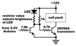
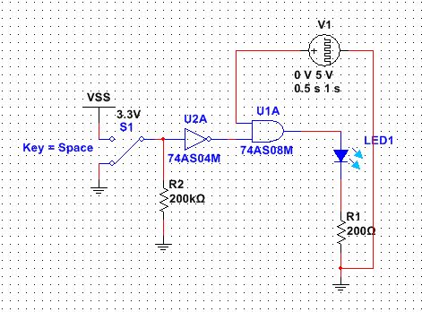
Im looking for a way to switch a 12v signal between 2 loads. One load will be a spark plug (Load 1), the other an LED + Resistor (Load 2). I need to be able to switch between the 2 loads by signalling through the Arduino 3.3v pin (HIGH or LOW). This is relatively simple, however the bit im struggling with is, I need the design to always have Load 1 enabled when the Arduino sends LOW (or Arduino is powered off/fails), and only switch to Load 2 when Arduino is HIGH.

Ive tried numerous circuits, NMOS + PMOS switched (which I cant really get the PMOS circuit to work with the 3.3v gate voltage) and using Opto-couplers. Can somebody give me some help? I need the response to be quite fast, though the maximum signal rate of the spark plug will at most be 150Hz.

Thanks
 

A spark plug will not work from only 12V. It needs THOUSANDS of volts.

Yes, it is the signal from the ECU to the coil pack to be more specific, this is only 12v, I am using another LED and resistor to model this part of the circuit. I just need to be able to divert this signal from the ECU to another load when the Arduino is HIGH.
 

Just checked, its only 5V @ 20mA, not totally 100% about it being 5V will double check that tomorrow. But say if it was 12V 20mA how can we proceed?
 

You provided no details so I guessed that the coil pack ground can be switched. I have it powered from 12V.
 

Attachments

  • coil pack or LED switch.png
    coil pack or LED switch.png
    7.6 KB · Views: 91

I would bet that you can find automotive "load switches"
for dirt cheap with TTL compatible input levels, good to
go. At least up to a few amps. Beyond this you'd want
a MOSFET driver to do the level shifting and a PMOS
pass FET if it's going to be DC or quasi-DC; a high side
driver (bootstrapped) and NMOS might be cheaper if a
minimum toggle rate can be guaranteed.

https://www.digikey.com/product-sea...t=0&page=1&quantity=0&ptm=0&fid=0&pageSize=25
 

Thanks for the reply, i will look into your method.
For now going with 5v, i think its much easier, this is a simple design i came up with using TTL. My only worry is, im not sure how much current is drawn from the voltage pulse generator when the AND gate output is 0. Looking at the data sheet i understand that only 20ma is drawn by the IC when short circuited. Anyone can clarify this?

2395056500_1393460218.jpg


And just to clarify, i am basically building a relay between the ECU and Coil Pack. This i because this uses low voltage like 5v. I am not permitted to touch anything past the Coil Pack due to the huge voltages. The LED and Resistor in my diagram are just a visual indication to what is happening on the output, in real life the output will be connected to the input of the Coil Pack.
 
Last edited:

I haven't used old fashioned TTL for about 39 years so I had to look it up.
The spec's for the 74AS04 shows that its resistor to ground must be 4k ohms or less, not 200k.
The minimum output logic high voltage of a 74AS08 is only 3V when it has a 5V supply and its load is only 2mA. Its maximum output logic low voltage is 0.4V when its current is 20mA.

What is that thing labeled as V1?
 
Thanks I was just guessing with R2. V1 is the ECU, provides a pulse signal or square wave output of varying frequency dependant on RPM of the engine. Also thanks for clearing up the 0v current draw.
 

Can you scribe this "12V signal" source ? If it is normally configured to drive the primary side of a ignition coil pack then you might be in for a surprise, as 1000V back EMF spike normally exists on this wire during the spark gap discharge. It may not be so simple to use this a your signal source.

You will need to cut off the 12VDC supply to ignition coil primary common connection.
 

I believe it is just a signal at 5v 20ma, the device is a vipec v88, in the manual it connects to an igniter, I can't see it actually driving the 1000v signal. But I can't say for sure and not sure how to confirm.
 

These are the specs
VX Ignition Specifications:
Ignition Drive High 20mA @ 5V
Ignition Drive Low 2A over current protected
Open Collector (not fly-wheeled) in auxiliary output mode
 

Status
Not open for further replies.

Similar threads

Part and Inventory Search

Welcome to EDABoard.com

Sponsor

Back
Top