marios90
Newbie level 1
Hi,
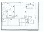
i need urgent help if you can help me. I am working on a project for which i am trying to built a circuit that will automatically compensate for impedance mismatch between two resistors by varying the current provided to each resistor so that the voltage across both different resistors will be the same. I have attached the circuit design. The total current in the circuit should not exceed 8mA. However, in building the circuit a get negative voltages across resistors R1 and R2 which mess up everything and i cannot identify the problem. Can anyone help me in pointing the problem?? I NEED HELP PLEASE!
The idea is that i have two fixed current sources providing 4mA current each and then a fully differential amplifier with a gain of 10 has as output the difference in voltage between R1 and R2 which is then fed to a transconductance amplifier for either injecting or drawing the appropriate current so that the voltage across R1 and R2 would be the same for a resistance tolerance of +-20%. However, i cannot understand why i get negative voltage across the resistors in practise as i have tried in multisim and it seems to work in simulation.