Continue to Site

Welcome to EDAboard.com

Welcome to our site! EDAboard.com is an international Electronics Discussion Forum focused on EDA software, circuits, schematics, books, theory, papers, asic, pld, 8051, DSP, Network, RF, Analog Design, PCB, Service Manuals... and a whole lot more! To participate you need to register. Registration is free. Click here to register now.

Passive UHF RFID Tags

Status
Not open for further replies.

zubii

Newbie level 4
Joined
Feb 11, 2014
Messages
7
Helped
0
Reputation
0
Reaction score
0
Trophy points
1
Activity points
51
Hi everyone,
I am new to the field of UHF Passive RFID tag antanna's.
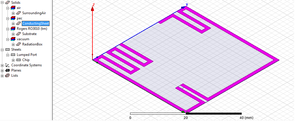
I am using HFSS tool to reproduce the tag antenna of a research paper.
I have made the structure and set all the parameters like substrate material, conductor thickness, (quater wavelength) radiation box, solution frequency 891 MHz and most importantly the chip impedance using lump port.

I am getting very bad results, S11 is very bad, not achieving antenna impedance if i change the lump port impedance the result remains the same? how is it possible, can anyone suggest me where m i doing the mistake?
 

pictures are always nice. is it resonating off frequency or not at all?
 
6470641100_1392288851.png


- - - Updated - - -

yes, its resonating but at 730MHz(S11= -2.8dB) where as in paper its resonating at 890MHz(S11= -8.5dB)
 
Last edited by a moderator:

How do you define S11?

As the the tag wants to look into a non-real impedance, any S11 normalized to a real reference impedance will not give good results. The tag needs to see a slightly inductive impedance to have a good match for both power receiving and back scattering. The values should be mentioned in the tag's full datasheet.

The antenna in the paper was very likely designed for a specific chip. If you use another chip, you need to design towards another non-real impedance.
 

Does the impedance match?

You can try to set the port impedance to 50Ohm and disable the normalization. Then just look at the simulated impedance.
From there you can calculate the S11 between the impedance of the antenna and the chip. This can also be done in HFSS with the output variables calculations so you can use it for optimizations.

(Some software does strange things if you use a normalization to a complex port impedance thus I usually avoid this.)
 

which sort of specific chip are you talking about. i mean i have tried various values of impedance but results have not changed. my concern is that the chip has no effect on the antenna you can see by changing values of impedance
 

@WimRFP,
1- For a good match at a specific frequency(891MHz) to achieve resonance, the tag(Inductive impedance, 16+j485 @ 891MHz) needs to be matched with IC(capacitive impedance, 16-j485 @ 891MHz). In power receiving from the reader, the IC(chip) impedance is the load impedance and in back scattering, antenna impedance is the load impedance.
2- Yes, you are right, the tag antenna is designed for a specific IC(chip) impedance and if the IC(chip) is changed, the antenna design needs to be changed as well.
3- I have tried without the normalization and getting positive S11, which is not desirable .

So i finally concluded that i need to re normalize it again.

Thanks for the comment.
 

What reference impedance did you use for "and getting positive S11"?
How do you define resonance?
 

1- I am not using any reference impedance.
2- Resonance, the frequency at which i m getting S11=-20dB.
 

Scattering parameters are based on a reference impedance (mostly real), so you must use a reference impedance, and that is very likely real. So you optimize your antenna to a real impedance that doesn't give a power match to the non-real input impedance of the chip.
 

So, if i don't normalize, i am getting the S11 in positive. where am i doing the mistake?
is the antenna not exactly matched to the chip impedance? (that's the reason i am not getting the research paper results)
 

If your tag has 16-j485 Ohms impedance (as provided by the manufacturer for best operation), you just need to design an antenna that has 16+j485 Ohms.

So forget S11, returnloss, VSWR, resonance, etc, just make sure your antenna has 16+j485 Ohms impedance. when done, you have a conjugated match between the antenna and the chip.

OT: the last time I did UHF RFID antennas, the imaginary part wasn't that high, are you sure you use the correct chip impedance?
 

yes, its 16-j485 Ohms.
Ok, i am trying to achieve the conjugate match.
The chip impedance is 16-j485 Ohms, so i need to set the lump port with resistance=16Ohms, reactance=-485Ohms, is that right?
If you have any example related to UHF RFID antenna, can you please share it with me? it would be very helpful.
 

No, that is not fine.

Just leave Zs = Zport = 50 Ohms, make sure that your Smith Chart marker shows impedance. Now design your antenna so that it reads 16+j485 Ohms (that is in the upper right part of the Smith Chart, near the edge).

As mentioned by Flanello also, software may behave strange when using complex reference impedances. With your current understanding I would not try complex reference impedances.

When you are finished, then you could use a complex port impedance, but make sure you understand your software first. Smith Charts in RF engineering are used virtually always with real Zs (or Zref), as transmission lines at RF have virtually real characteristic impedance.

I know how to use complex source impedances in IE3D, but not in CST.
 

Status
Not open for further replies.

Similar threads

Part and Inventory Search

Welcome to EDABoard.com

Sponsor

Back
Top