Continue to Site

Welcome to EDAboard.com

Welcome to our site! EDAboard.com is an international Electronics Discussion Forum focused on EDA software, circuits, schematics, books, theory, papers, asic, pld, 8051, DSP, Network, RF, Analog Design, PCB, Service Manuals... and a whole lot more! To participate you need to register. Registration is free. Click here to register now.

[PIC] Problem regarding to config bits in pic16f887

Status
Not open for further replies.

jigar@19021993

Newbie level 4
Joined
Oct 25, 2013
Messages
6
Helped
0
Reputation
0
Reaction score
0
Trophy points
1
Activity points
51
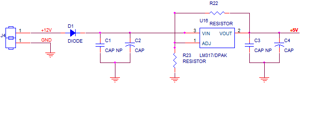
i m using pic 16f887 controller. I hv problem with configuration bits. my project must work on 12v but currently it is working on 5 v. so can anyone help me to set configuration bits.
i use external crystal of 10 MHz.
i can not identify my problem, i think it shold be in configuration bits... Help me..
 
Last edited:

You cannot make the PIC16F887 work on 12V by changing the configuration bits (or anything else). Its absolute maximum supply voltage is 6.5V. Do you have a voltage regulator to reduce that supply voltage? Maybe that is the problem.

Please provide a schematic showing what you are trying to do.

John
 

no sir, 12v is main power supply to my project. my controller operate on 2.5v, which should be operate on 5v. so problem is in config bit.

we use voltage regulator ic that conver 12v to 5v. so if we give 12v then IC convert it to 5v, similarly
if we give 5v then ic convert it to 2.5v and on 2.5v my program is successfully run.
 

If you mention your application, schematic diagram, source code and the compiler it would be easy to help you.
 

...my controller operate on 2.5v, which should be operate on 5v. so problem is in config bit.

It is not clear to me what voltage you want or have. Are you saying that your voltage regulator is only giving 2.5V and you want 5.0V, or are you trying to operate the PIC at 2.5V? If it is the voltage regulator, please post a schematic.

If you want to operate the PIC at 2.5V , are you sure it will operate at 10 MHz and 2.5Vdd?

Capture.PNG

John
 

Minimum voltage required for the PIC16F887 is 2V. I think you're referring about the Brown-out reset. But what I can't understand is if it works for 2.5V it should work for 5V also. If you have set brown out reset for 2.1V the pic will be rested if the voltage drops below 2.1V. If you have set it for 4V the PIC will be reset if it fall below 4V.

Why have you put a resistor between input and the output?

I think no one can understand your problem. If you can explain your problem clearly, someone could help you.
 

You say, your 16F887 is presently working with 2.5 V supply and should be used at 5V in the new design.

There's no configuration fuse that must be changed in this case, unless you plan other modifications that haven't been reported yet.

A confusing point in your post is the said 10 MHz crystal, because 2.5 V operation is specified for 8 MHz maximum clock frequency.
 

Regarding Post#6, what are the values of R22 and R23? You show +5V as the output. Is that what you measured it to be, or what you want it to be? If you measured it to be 5V, what is the problem? If you want it to be 5V, but only observe 2.5V, then your resistor values are incorrect.

John
 

Status
Not open for further replies.

Similar threads

Part and Inventory Search

Welcome to EDABoard.com

Sponsor

Back
Top