toyonline
Member level 2
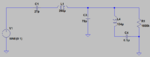
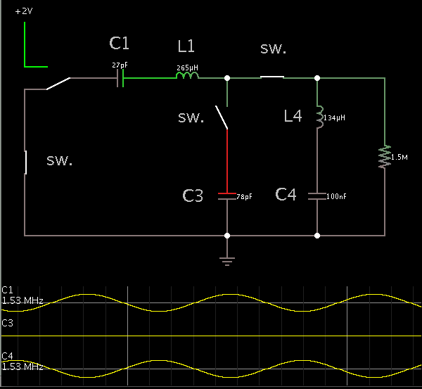
Hi, I am working on fabrication of a coupled LC resonance circuit. It is like in attachment. From simulation, I know there are two resonant frequencies f1 and f2. Change capacitor C3 will give different ratio of f1:f2. From the simulation, I know as C3 approaches to 78 pFarad, the ratio is approaching 1:2, which is what I want.
But still I have some problems. How could I figure out a physical explanation of the existance of double frequencies in this coupled LC resonance circuit? Is it any qualitative way to 'predict' those two frequencies? Or at least a explanation of tendency of the ratio change under different capacitance and inductance.
The only thing I could understand is, if C3 approaches infinity, then C3 will behave like a open part, which will change the overall circuit as if C3 is not exist. Then the circuit could be understand as a simple series LC circuit, which possessing a single frequency. Am I right?
Would you please help me to understand such a circuit physically? Thank you guys:smile:
- - - Updated - - -
Here is the attached circuit.
Hi, I am working on fabrication of a coupled LC resonance circuit. It is like in attachment. From simulation, I know there are two resonant frequencies f1 and f2. Change capacitor C3 will give different ratio of f1:f2. From the simulation, I know as C3 approaches to 78 pFarad, the ratio is approaching 1:2, which is what I want.
But still I have some problems. How could I figure out a physical explanation of the existance of double frequencies in this coupled LC resonance circuit? Is it any qualitative way to 'predict' those two frequencies? Or at least a explanation of tendency of the ratio change under different capacitance and inductance.
The only thing I could understand is, if C3 approaches infinity, then C3 will behave like a open part, which will change the overall circuit as if C3 is not exist. Then the circuit could be understand as a simple series LC circuit, which possessing a single frequency. Am I right?
Would you please help me to understand such a circuit physically? Thank you guys:smile: