Continue to Site

Welcome to EDAboard.com

Welcome to our site! EDAboard.com is an international Electronics Discussion Forum focused on EDA software, circuits, schematics, books, theory, papers, asic, pld, 8051, DSP, Network, RF, Analog Design, PCB, Service Manuals... and a whole lot more! To participate you need to register. Registration is free. Click here to register now.

capacitive dual power supply

Status
Not open for further replies.

bmandl

Full Member level 4
Joined
Feb 26, 2010
Messages
207
Helped
3
Reputation
6
Reaction score
3
Trophy points
1,298
Location
Slovenia
Activity points
2,965
Hello,
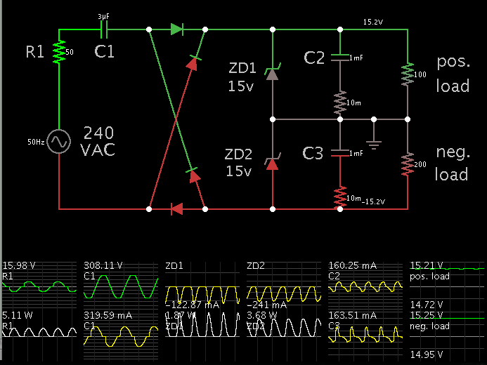
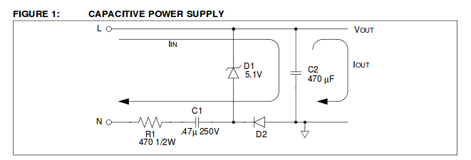
I need some low current power supply for my project with opamps, that need dual power supply. Is it possible, to make such supply with two capacitive power supplys? Would this design, that I drew work? Do I need negative voltage regulator on bottom line, or is it good as it is?

PS.: don't mind capacitor and resistors values, I didn't determined them yet.

cap_dual.PNG
 

Not sure what you mean by capacitive power supply, but I don't think that circuit will work properly. An AC source connected to two separate bridge rectifiers doesn't result in isolated outputs which can be connected in series.

A better approach would be to use two half wave rectifiers to generate positive and negative rails (this is sometimes called a voltage doubler).
 

My objective is, to modify this power supply to produce double stabilized output? How can i achieve that?
 

Can this be done with two voltage regulators instead of zenner diodes?
 

Better obtain a regular transformer.
The power supply can be "incompatible with life" especially if you intend to use it for any kind of effects for musical instruments. (especially guitars, that are more or less grounded).
 

Can this be done with two voltage regulators instead of zenner diodes?

The zener diodes are a convenient way to do two things:

(a) provide a path for current to go in both directions, because the capacitor requires this.

(b) ensure that your components will not be exposed to unpredictably high volt levels, as could happen when loads are disconnected.

If you wish, you can use 15V zeners, and then add the regulator IC's (at the same position where my schematic shows the loads).

Your negative supply will need a negative regulator. A 7912 instead of a 7812.
 

Ok, thank you all for advices. @ZASto, I don't want to use transformer in my application, because I don't need much current and I want my device to be light and cheap. I made new schematic. Will this one do the job?
And I have one more question. How do you advice me, to select capacitor and resistor, to achieve as much current as possible?

cap_dual.PNG
 

The ground symbol in the schematic seems to be misleading. The circuit is carrying high voltage against ground and must be neither grounded nor touched.

How do you advice me, to select capacitor and resistor, to achieve as much current as possible?
You need to understand some basics about electronic circuits and calculate the component values respectively. At present, the values are completely wrong.
 

@bmandl:
That circuit won't work if you connect it to ground as shown. If you don't connect it to ground, it can kill you if you touch any part of it. Maybe you missed ZASto's comment about "incompatible with life".

I don't need much current...

How do you advice me, to select capacitor and resistor, to achieve as much current as possible?
So you don't need much current, but you want as much current as possible? Could you be a bit more clear about the requirements.
 

I need as much current, that power supply like this can provide. And I know, that it can't provide much more than maybe 200 mA with 12 V at output and this is enough for me. So, I must not ground it and therefore I can not protect it. But I don't understand, why not. 0V point is supposed to be, where earth is am I not correct?
 

I have adjusted values so the supply can power heavier loads. By adding a full-wave bridge it uses power in both AC directions.

The negative load is a higher ohm value, to show how ZD2 is forced to dissipate more power as heat. With loads disconnected, the zeners dissipate power of 4.9 W peak.


So, I must not ground it and therefore I can not protect it. But I don't understand, why not. 0V point is supposed to be, where earth is am I not correct?
If you connect it to ground:
Current will flow from mains live to ground and trip a circuit breaker in your house (assuming there is some sort of earth leakage system or residual-current circuit breaker).

If you do not connect it to ground:
There may be very high voltage on the "low voltage" terminals. This is a serious shock hazard. Also, if you connect the power supply to any other equipment that is grounded, that equipment may be damaged and the circuit breaker will trip (as above).
 

Every single schematic in that document is wrong. If any of them were plugged into a wall socket and switched on, C2 and the diode(s) would explode almost instantaneously.

I'm not making this up. Look at the schematics. In every case the "low voltage" resevoir capacitor is connected directly between Live and Ground.

edit: So much for safety as well. In each case, the "+5V regulated output" is also connected directly to mains Live.

edit2: In fairness to the idiot who wrote that document, he does mention that all of the circuits shown need to be isolated from the mains with an isolation transformer. Of course doing that defeats the whole purpose of a "transformerless" power supply.
 
Last edited:

@godfreyl:
If you are talking about C2, then you are WRONG. It is on the Low voltage side, i.e. after series connection of R1-C1 on Fig.1. or after resistor R1 on Fig.5. or after R1-(R2//C1).
If you have not noticed, there's a Zenner D1.
So much on your knowledge :lol:
 

So much on your knowledge :lol:
Maybe you should switch your brain on before insulting other people or questioning their knowledge.

Here's the first schematic from that document:


Please note:
A) There is a direct connection between mains live on the left and Vout on the right.
B) C2 is connected directly between mains live and ground.

Is there any part of that you don't understand?
Or do you just not see any problem with it?
 
Last edited:

Ok, please don't argue now about that document, it's not worth it.
Practically, about how much current do you think I can get from supply like that if I want symmetric 12V supply and one 5V for microcontroller?
What are other cheap and safer options for transformerless power supply (and of course, simple)?
 

Maybe you should switch your brain on before insulting other people or questioning their knowledge.

Here's the first schematic from that document:


Please note:
A) There is a direct connection between mains live on the left and Vout on the right.
B) C2 is connected directly between mains live and ground.

Is there any part of that you don't understand?
Or do you just not see any problem with it?

No I don't see any problem, you are missing obvious.
If the input frequency is 50 Hz, then the impedance of C1 is 6772 Ohms, on 60 Hz is 5643 Ohms. Add to that 470 Ohms of R1.
Zenner is used as an ordinary shunt regulator.
You can even exchange L and N and the circuit will still work the same way.

The ground symbol on the circuit diagram DOES NOT represent the grounding terminal of the household power outlet. It is just a reference point for making measurements and explaining the working of the circuitry.

Anyway, it is LETHAL circuit as there is NO GALVANIC isolation from mains.

Some 20+ years ago, a friend of mine, guitar player and singer died on stage when he grabbed microphone while holding his guitar with other hand.

That's main reason why I stated that this kind of power supply can be a real killer, based on bmandl's avatar.

- - - Updated - - -

@bmandl:
capacitive dual power supply te lahko ubije kot zajčka :)
 

Ok, I changed my mind. I will use small, cheap 10VA double secondary winding transformer, which after all isn't so heavy and it's safer. I will also use 1117 3.3V regulator from texas instruments, because I will be using NOKIA 330 display. This is my schematics:
power_dual.PNG
 

Status
Not open for further replies.

Similar threads

Part and Inventory Search

Welcome to EDABoard.com

Sponsor

Back
Top