themaccabee
Full Member level 4
Dear Experts,
I want to design a HF current probe,
Aim : Is to relatively measure the cable current radiation to estimate if my fix on PCB ,is working or not.(For pre compliance testing purposes)
Materials I have : Wurth Toroid Core 74270097 ,Teflon Wire, BNC connector
Equipment i have : An Old Spectrum Analyzer ESA-L1500A , 75Ohm, 1 MHz-1.5GHz
Input Specifications of Spectrum Analyzer : 75Ohm,75dBmV(0.4W) MAX/ 100v DC MAX
I was trying to follow the section DIY CURRENT PROBES in https://www.interferencetechnology.com/the-hf-current-probe-theory-and-application/
some details are not clear there , may be it is obvious,
1) Is it ok to use multi-stranded teflon wires
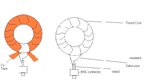
2)The one end of the wire after winding should be connected to BNC connector center point and the other to the BNC shield correct?
3)They are mentioning a copper tape to be put over the windings as electrostatic shield.Should it be connected to BNC shield Ground?
Since my spectrum analyser is 75 Ohm input impedance & I've no option for VNA or similar device to estimate the transfer function of the probe
4) Is it necessary to convert or put 50 to 75 ohm adapter in between? i dont actually have one and commercial ones are pretty expensive for me to afford.
5)Or if i can work in 75 Ohm impedance system, what else should i take care?
6)The BNC connector to the Toroid core be 75 Ohm or 50 Ohm?
7) Is there any chance that i will be overloading ( destructively) the spectrum analyzer input by any chance?what should i take care?
8) Is it ok to proceed without transfer function estimation of the probe, my idea is that observing the spectrum analyser with and without cable inside so that i can see the base line noise first ,and then inserting the cable and check the effect of rework on board by maintaining the setup same.
Any suggestions will be really helpful,
Thanks
I want to design a HF current probe,
Aim : Is to relatively measure the cable current radiation to estimate if my fix on PCB ,is working or not.(For pre compliance testing purposes)
Materials I have : Wurth Toroid Core 74270097 ,Teflon Wire, BNC connector
Equipment i have : An Old Spectrum Analyzer ESA-L1500A , 75Ohm, 1 MHz-1.5GHz
Input Specifications of Spectrum Analyzer : 75Ohm,75dBmV(0.4W) MAX/ 100v DC MAX
I was trying to follow the section DIY CURRENT PROBES in https://www.interferencetechnology.com/the-hf-current-probe-theory-and-application/
some details are not clear there , may be it is obvious,
1) Is it ok to use multi-stranded teflon wires
2)The one end of the wire after winding should be connected to BNC connector center point and the other to the BNC shield correct?
3)They are mentioning a copper tape to be put over the windings as electrostatic shield.Should it be connected to BNC shield Ground?
Since my spectrum analyser is 75 Ohm input impedance & I've no option for VNA or similar device to estimate the transfer function of the probe
4) Is it necessary to convert or put 50 to 75 ohm adapter in between? i dont actually have one and commercial ones are pretty expensive for me to afford.
5)Or if i can work in 75 Ohm impedance system, what else should i take care?
6)The BNC connector to the Toroid core be 75 Ohm or 50 Ohm?
7) Is there any chance that i will be overloading ( destructively) the spectrum analyzer input by any chance?what should i take care?
8) Is it ok to proceed without transfer function estimation of the probe, my idea is that observing the spectrum analyser with and without cable inside so that i can see the base line noise first ,and then inserting the cable and check the effect of rework on board by maintaining the setup same.
Any suggestions will be really helpful,
Thanks