uoficowboy
Full Member level 3
- Joined
- Apr 4, 2009
- Messages
- 169
- Helped
- 6
- Reputation
- 12
- Reaction score
- 5
- Trophy points
- 1,298
- Location
- Seattle, Wa, USA
- Activity points
- 2,964
Hi - I have a 0-2.8V signal with about 75K source impedance. That impedance is not tightly controlled, however. I would like to scale the 0-2.8V signal down to about 0-1.85V. I need the scaled signal to to be low impedance (less than 1K).
This is for an audio signal - a DAC is generating a 0-2.8V signal. The DAC has an output impedance of about 75K. I need to scale that 0-2.8V signal down to 0-1.85V for an audio amplifier. The audio amplifier has about 100K input impedance. I need to AC couple my input to the audio amplifier. I have available to me a 2.8V supply as well as a 3.1V-4.2V supply.
I could do this pretty easily with two op-amps - the first op-amp would buffer the DAC, the output of the buffer would be divided down with a resistor divider, and then that voltage would again be buffered. But op-amps are expensive - that circuit would cost me about $0.10/board.
I have an alternative solution, where I divide down the output of the DAC with a very large resistance divider (much larger than the DAC's output impedance), then essentially buffer it with a common collector amplifier using a PNP BJT. In simulation this seems to work OK. I have not tried it out in the real world yet, and I'm concerned that there could be problems that I'm missing. This is much cheaper than the op-amp - probably total cost is $0.02 or so.
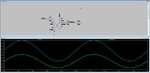
I've attached a screenshot of my simulation. VDAC is the voltage coming from the DAC, R6 is the DAC's output impedance, and R10 is the input impedance of my audio amplifier.
What do you all think? Is my solution OK? Can you suggest an alternative method that would work better? Thank you!
This is for an audio signal - a DAC is generating a 0-2.8V signal. The DAC has an output impedance of about 75K. I need to scale that 0-2.8V signal down to 0-1.85V for an audio amplifier. The audio amplifier has about 100K input impedance. I need to AC couple my input to the audio amplifier. I have available to me a 2.8V supply as well as a 3.1V-4.2V supply.
I could do this pretty easily with two op-amps - the first op-amp would buffer the DAC, the output of the buffer would be divided down with a resistor divider, and then that voltage would again be buffered. But op-amps are expensive - that circuit would cost me about $0.10/board.
I have an alternative solution, where I divide down the output of the DAC with a very large resistance divider (much larger than the DAC's output impedance), then essentially buffer it with a common collector amplifier using a PNP BJT. In simulation this seems to work OK. I have not tried it out in the real world yet, and I'm concerned that there could be problems that I'm missing. This is much cheaper than the op-amp - probably total cost is $0.02 or so.
I've attached a screenshot of my simulation. VDAC is the voltage coming from the DAC, R6 is the DAC's output impedance, and R10 is the input impedance of my audio amplifier.
What do you all think? Is my solution OK? Can you suggest an alternative method that would work better? Thank you!