Continue to Site

Welcome to EDAboard.com

Welcome to our site! EDAboard.com is an international Electronics Discussion Forum focused on EDA software, circuits, schematics, books, theory, papers, asic, pld, 8051, DSP, Network, RF, Analog Design, PCB, Service Manuals... and a whole lot more! To participate you need to register. Registration is free. Click here to register now.

[SOLVED] TX-2B & RX2B circuit problems explanation required

Status
Not open for further replies.

DebarghyaChaudhury

Newbie level 6
Joined
Jan 8, 2014
Messages
11
Helped
0
Reputation
0
Reaction score
0
Trophy points
1
Activity points
115
Hello,
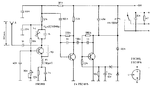
I am trying to build my physics project for my board exams and basically it is a rc car circuit ,
I have come across this pdf before building the circuit and have taken the ic's from a toy car itself :

https://www.google.co.in/url?sa=t&r..._EYg4eEnX91yq-d8A&sig2=ZZp_5TT-meWkFtzsbTf3oA

but after gathering all the components we could not find the following materials and have used the corresponding replacements :
> Inductor- 6.9uH instead of 6.8uH
>Capacitor- (a) 4.7P instead of 4P
(b) 18.2P(10P & 8.2P in series) instead of 18 P
(c) 470P instead of 501P
>Resistor- 3.2MegaOhms(1MO & 2.2MO) in series instead of 3.9 MO
>KJE 26.6017125 MHz instead of XTAL 27 MHz

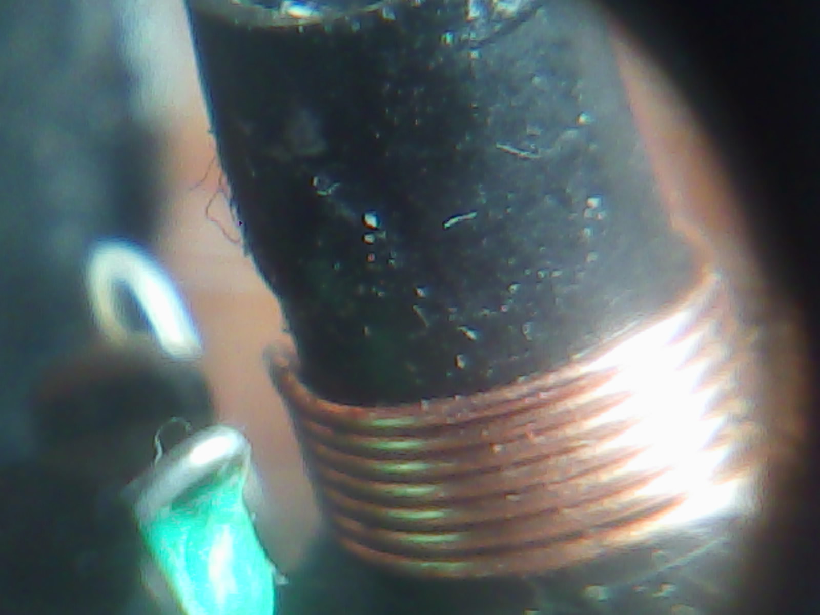
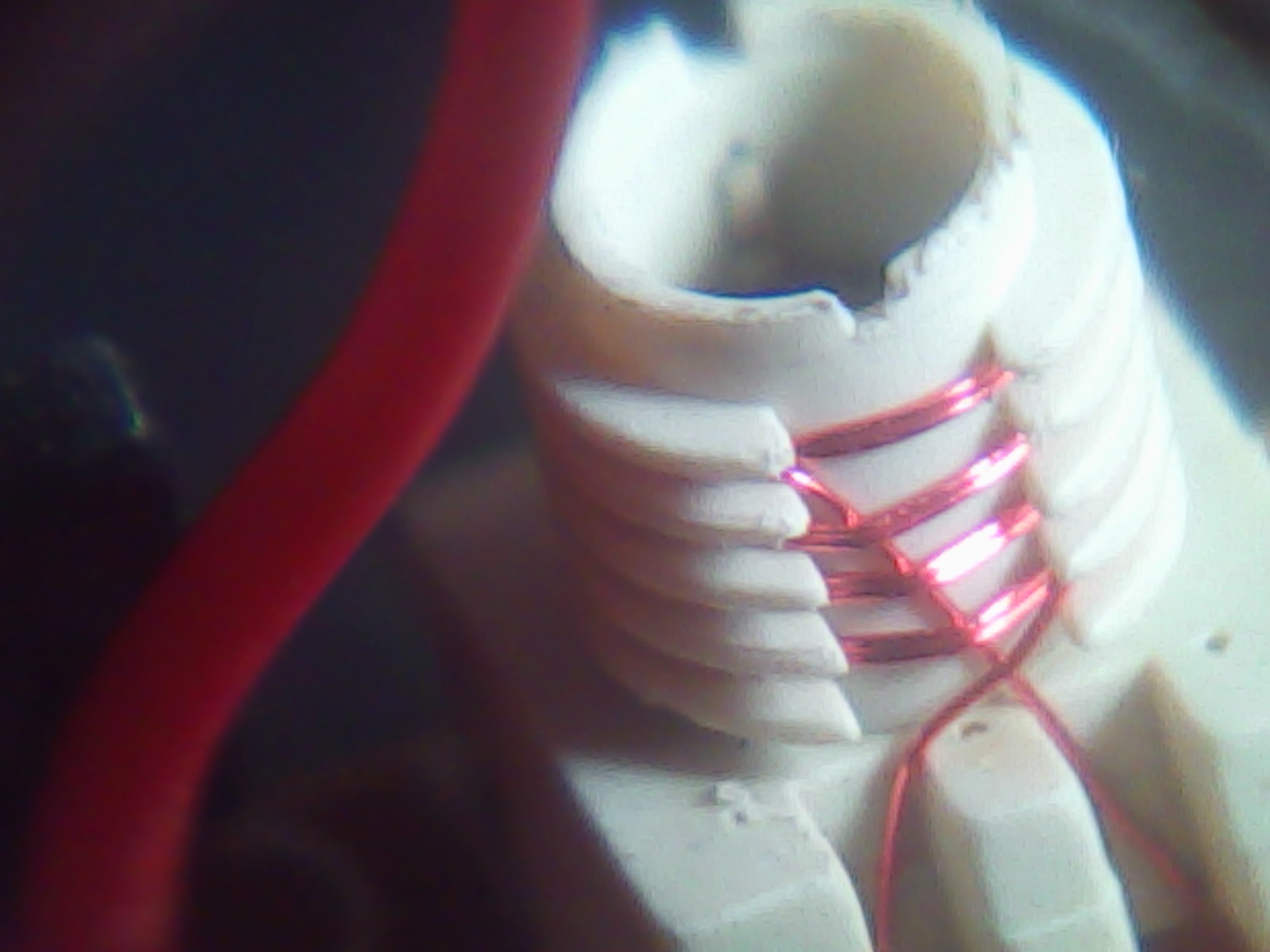
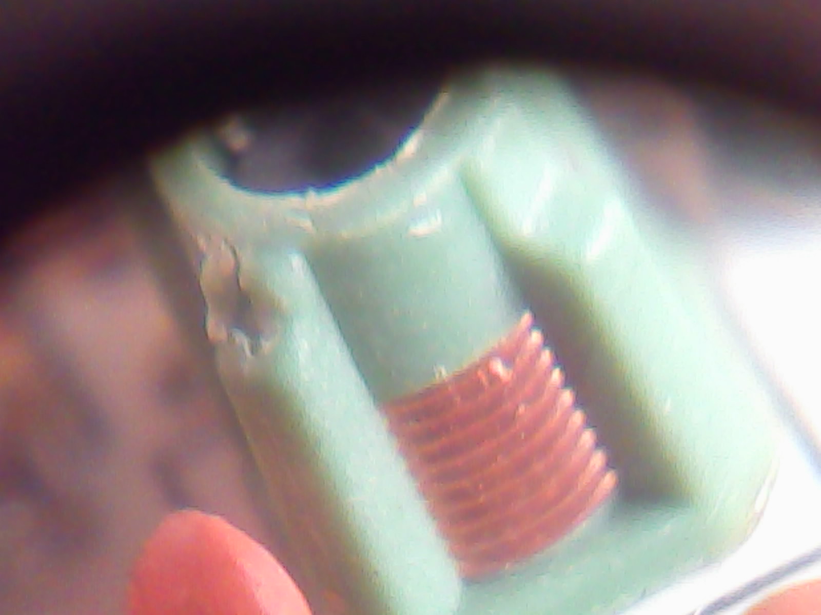
also I am not clear about the inductor labelled " 7T 0.3mm(phi) x 5mm (Core)" and the size of the antenna. Please explain these.

I have compiled the whole circuit on a vero board and now it is not working.....it is my 1st electronic project and I am completely at a loss
kindly can anyone point me where I may have gone wrong?
 
Last edited:

Transmitter aerial ~1m, receiver aerial ~ .3m. Changing the frequency of the Tx will put you out of band (but should not stop it working). Build a diode detector probe, and measure the voltage between the aerial and the ground of the TX, when you send data, you should be able to see a small voltage. Adjust the circuit for a maximum. Now you have to get the receiver to lock up, the coil you are not sure about is the main "tuning" component for the RX, so try adding/subtracting turns and with some luck the RX will spring into life.
Frank
 
To make 18.2pF you put two capacitors in series instead of IN PARALLEL so your total of 4.5pF is much too low.
 

Re: TX-2B & RX2B circuit problems explanation required

Sorry I could not get your point could you please elaborate your point a little more?......I mean in the circuit it was given 18P so I put those in series so that they add up to 18.2P.

If I put them in parallel then it will be 1/R1 + 1/R2 so it will be decreased if I am correct. Thanks in advance :)

- - - Updated - - -

Thanks chuckey!!! but are rest of the replacements ok like the 6.8uH inductor and 470P instead of 501P and 3.9MO especially?...............also what do you mean by "Adjust the circuit for a maximum" part.

thanks again!!
 

Re: TX-2B & RX2B circuit problems explanation required

Sorry I could not get your point could you please elaborate your point a little more?......I mean in the circuit it was given 18P so I put those in series so that they add up to 18.2P.

If I put them in parallel then it will be 1/R1 + 1/R2 so it will be decreased if I am correct.
No, you are WRONG.
The values for parallel capacitors are added together. Stray capacitance of the wiring adds even more capacitance.
(The values of series resistors are added together).

what do you mean by "Adjust the circuit for a maximum"?
He said to build a "diode detector probe" which measures RF power output. But the simple transmitter circuit has nothing to adjust. The transmitter is simply an amplified crystal oscillator that is not adjustable. The simple receiver also has nothing to adjust. You guess that it is tuned to the transmitter frequency.

It is a very cheap and simple circuit. Its range might not be far.
Its steering is bang bang (full right, center or full left). Its speed is also bang bang (forward, turbo forward, reverse or stop).

My radio controlled model airplanes have proportional controls of rudder, elevator, ailerons and speed. The flaps are bang bang (partial, full or off).
 
Re: TX-2B & RX2B circuit problems explanation required

Oh....thank you very much !!!.................. but can u tell me if the rest of the components are ok? and if I'm right the coil is 7 turns 0.33mm copper wire with iron core of 5mm diameter ??
 

An iron core is used for low frequencies. A ferrite core is used in this high frequency radio project.

You are using the wrong capacitors and probably you will not find a suitable ferrite core.
Then I suggest that you buy one of these cheap radio controlled cars and use its parts for your project.
 

thanks man , but I have already bought 1 but the car runs on 6V so the capacitor values are not the same I HAVE to get the circuit run so badly so if possible can u please suggest for the correct replacements.................I would really appreciate it. I've actually got 2 cars, the old one runs on 9V and has the required 7 turn coil but its transmitter which runs on 3V doesn't have any coil ! don't know why instead it has a 4.6 inductor
and the new car got coils on both the transmitter and receiver but the RX circuit has got the right diameter but with 9 turns ,while its transmitter has 9 turns but the diameter's different(its smaller than 0.3 mm maybe 0.1mm) and its got like 0.5 mm gapping but 1 thing that all of the coils have in common is they more or less have 5mm ferrite core. So kinda in the middle of a dilemma right now and don't know what to do and would really like to get some help around.


Don't get me wrong man but there is some truth to your answer , I don't understand/know much about the RF circuit so thats why I'm asking for help cause its not working and I HAVE to get it to WORK by any means.I just want to know that if my replacements are correct, if not correct then what should I use in place of them inorder to get the circuit to work.........I want to know which components of the circuit are crucial and can affect the proper working of it, thats all.

I really appreciate your helping me cause I'm just a beginner to electronics and getting this project down really counts. Thanks in advance !!
 

A coil that is the proper size with a proper core (there are many different cores available and they are all different), the value of the capacitor parallel with it and the parallel stray capacitance of your wiring (a breadboard has lots of stray capacitance) determine the tuned frequency. The core can be screwed into or out of the core to tune the frequency a little.
Maybe your receiver is on a different frequency from your transmitter because you used the wrong parts. That is why I said to use the parts from a purchased radio controlled car.
 
Then can I use 497P(470P & 27P in parallel) in place of 501P and 4P(1P & 3P) in place of my 4.7P in the circuit? Also does that mean that the 6.9uH instead of 6.8uH and 3.2MO instead of 3.9MO can be accepted?
I got the coils and also I'm replacing the 26.6 MHz crystal with 27.145 MHz so thanks for all the explanation.
Chinese mark their capacitors oddly.
I think the Chinese schematic says 102P instead of 10 followed by "2" zeros which is 1,000P. They say 103P instead 10,000P.

You should find the schematic from another IC manufacturer or from a toy manufacturer.
Here is another schematic of a 27MHz toy car. It uses 20nF (20,000pF) but your schematic uses 203P (20 followed by "3" zeros) which is also 20,000pF.
 

Attachments

  • toy_ car_regen_rx.gif
    toy_ car_regen_rx.gif
    12.6 KB · Views: 331

Status
Not open for further replies.

Similar threads

Part and Inventory Search

Welcome to EDABoard.com

Sponsor

Back
Top