Continue to Site

Welcome to EDAboard.com

Welcome to our site! EDAboard.com is an international Electronics Discussion Forum focused on EDA software, circuits, schematics, books, theory, papers, asic, pld, 8051, DSP, Network, RF, Analog Design, PCB, Service Manuals... and a whole lot more! To participate you need to register. Registration is free. Click here to register now.

Brightness problem with Panasonic TC14-S4RC

Status
Not open for further replies.

Fagenhauser

Newbie level 3
Joined
Jan 4, 2014
Messages
4
Helped
0
Reputation
0
Reaction score
0
Trophy points
1
Activity points
33
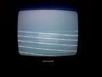
I have a Panasonic TC14-S4RC CRT TV that has a fluctuating brightness. It also shows about 10 bright diagonal retrace lines on an otherwise grey display. Tapping the PCB causes changes in the brightness but also without tapping the brightness changes. When the brightness becomes too high the tv switches off. I disconnected the control circuit that goes to a pin on the microcontroller called ABL. With this line disconnected tapping the PCB still causes brightness to change but the tv is not switched off anymore. All bias voltages seem alright. Could it be the heater, how can I check this? Could a dried up elco cause this problem, could tapping change capacitance or is a microcrack in a PCB-trace more likely? I only used a DMM so far. Many thanks for any suggestions that would help fix this problem.
 

It's very unlikely to be the heater. When the heater voltage drops the picture dims but also becomes much larger than normal. It sounds like you ave a dry joint somewhere , possibly on the CRT base PCB. When you say 'grey display' do you mean there is no picture and you only see a plain grey background?

Brian.

Thank you for your reply, I attached an image of the display, you only see a couple of the retrace lines but that is because of the camera I took the picture with. I have no signal connected to the tv. I tapped the PCB that is mounted directly on the CRT neck but that doesn't cause any changes in brightness, it is the main PCB where tapping influences brightness. With a dry joint you mean that a soldering doesn't make proper contact anymore? What circuits influence brightness, where should i look for "dry joints"?
 

Attachments

  • display retrace.jpg
    display retrace.jpg
    47.5 KB · Views: 89

The photograph is better than a thousand words!

Yes, a dry joint is a solder connection that has broken. It happens often if a TV has been jolted and one of the heavier components on the board has stressed the joint and cracked it. Solder is basically a tin alloy and isn't particularly strong, it cracks easily. They also tend to form around the pins of components that run hot, the expansion and contraction as the temperature changes eventually pulls the pin away from the solder blob. The usual clue is that tapping the board opens and closes the gap, although not completely in some instances, and temporarily reconnects the component.

I suggest you look on the solder side of the board for bad joints, concentrate on the pins of the physically bigger components and anywhere you see any discolored areas of the boards. The classic bad joint will have a circular break around the pin but they can sometimes be hard to spot.

If you can't see anything wrong, give some more information, for example, is the sound working normally? does the brightness control have any effect at all?

Brian.


Thank you Brian,

The sound works just fine. The problems started with incidentally loosing the channel and getting a display as shown on the image and then the TV eventually switches off. Turning the TV on again or off-on a couple of times would sometimes solve the problem as well as hitting the cover a few times. Loosing a channel or a sudden switching off of the TV became more and more frequent. I noticed that loosing a normal display occurred often when a channel shows a lot of white (e.g. a documentary of the antarctic). I remember that turning the TV on it's side would sometimes get the channel back. I will look for the solderings tomorrow. Thanks so far for your advice.

- - - Updated - - -

Thanks Brian,

the TV started losing the channels more frequently over time and when it does loose a channel it shows the display as on the image i send. Hitting the cover would sometimes get the channel back or even tilting the TV. The audio is good, even if the TV doesn't display the channel. I'll check for bad solderings tomorrow, thanks so far for your help.
 

Status
Not open for further replies.

Part and Inventory Search

Welcome to EDABoard.com

Sponsor

Back
Top