Continue to Site
Follow along with the video below to see how to install our site as a web app on your home screen.
Note: This feature may not be available in some browsers.
V1 should NOT be connected between ground and gate, it should be between cathode and gate.
I am sorry, I am confused. Do you mean to say that the ground should be disconnected from the negative of the Triggering Source & the cathode of SCR?
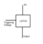
Actually, I wanted to replace SCR for flip-flop SR latches in a circuit as shown in the diagram. Of course, the negative of the triggering source is common ground. How shall we use an SCR to get 9V at the output?
Thanks for the help.

Does the load have to be grounded?
Post the .asc files for your simulations (along with the scr model and icon files).
I also need the SCR.asy symbol file.

Yes, it is actually the base-emitter drop of the NPN equivalent transistor in the SCR (look at the SCR equivalent circuit).Thanks for your help.
Just a last question, is the output 8.3V because of the usual 0.7V drop caused by a diode (in this case within the SCR)?