docosama
Newbie level 2
Hi there
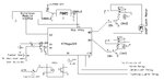
I have designed a 433Mhz wireless controlled Car security system with door locking/unlocking facility. It is controlled by AtMega328P Microcontroller. Circuit diagram is attached. I have uploaded a basic sketch in the Atmega328 which reads the code from the 433Mhz receiver module and the locking / unlocking relays work well without Door locking motor attached. However, when I attach the locking motor, Microcontroller restarts with each relay latch. I have set the latching time for the relay as 1 second. I dont know why the system restarts and couldnt figure out where is the fault. I need help.
Initially I thought that when motor runs, the voltage drops and as a result, microcontroller resets. So I have upgraded the capacitors attached before and after to 7805 to 1000uf. This helped a little bit but still the system resets with repeated testing.
Once this problem gets solved, i have a plan to add a GSM mobile with the AtMega328 so to lock/unlock car doors using SMS. And at the end, immobilizer system controlled using GSM mobile commands.