jean12
Advanced Member level 2
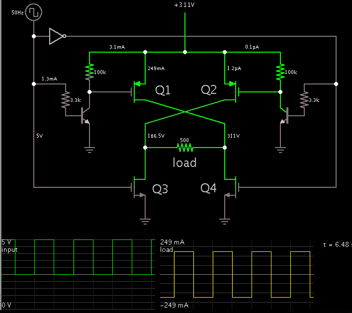
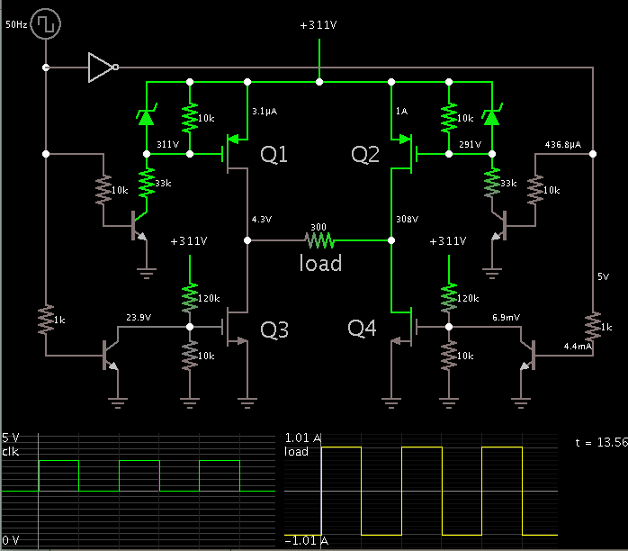
Hello there ,can anyone please help me to generate a signal which I can use for controlling my H-bridge made by IRFP460Z at 440VDC;I want to get 220VAC/50Hz;please help.
I tried to use the technics of Tahmid blog with SPWM but I failed I am getting nothing at the output.
Thanks.
I tried to use the technics of Tahmid blog with SPWM but I failed I am getting nothing at the output.
Thanks.