Continue to Site

Welcome to EDAboard.com

Welcome to our site! EDAboard.com is an international Electronics Discussion Forum focused on EDA software, circuits, schematics, books, theory, papers, asic, pld, 8051, DSP, Network, RF, Analog Design, PCB, Service Manuals... and a whole lot more! To participate you need to register. Registration is free. Click here to register now.

sallenkey Lowpass filter designing

Status
Not open for further replies.

patan.gova

Full Member level 3
Joined
Dec 19, 2011
Messages
172
Helped
4
Reputation
8
Reaction score
0
Trophy points
1,296
Activity points
2,776
Hello,
I was replacing a active Lowpass filter with a sallen-key lowpass filter but the sallenkey-filterLPfilter output was a 2.98V(DC) while the active lowpass filter was having a good pulse output.

Activelowpass filter **broken link removed** sallenkey-Lowpass filter **broken link removed**
The sallenkeyLPfilter used here was designed in the TI filterpro for a cutoff freq of 3Hz as shown here.
can someone explain why there is a difference in working between the two.
 

**broken link removed**
Here they are.
 

Both schematics are incomplete:
a) Are you using a single-ended supply or a split supply?
b) What is the supply voltage?
c) What opamp are you using?
d) What is the DC bias voltage at the input?
 

a)single ended supply
b)3v
c)OP484
d)input is from a lowpass filter(whose input is the output of phototransistor)
the below image describes a bit about the working of active LPfilter by using a Op484 opamp **broken link removed**
the image has 3 signals and are 1)green signal:eek:
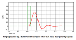
utput of phototransistor is at 2.9V2)red signal:Output of HPfilter3)bluesignal:eek:utput of LPfilter
The sallenkey filter was given the input as shown with red signal in the image but th output was a Dc of 2.9V.
 

patan.gova,
what is the dc voltage at the Sallen-Key-filter input?
What do you expect at the opamp output taking into consideration a dc gain of (1+R4/R3) ? Not very hard to compute.
Who has computet this large gain value?
In post#1 you have mentioned TI filter software. As far as I know, they require to fix the gain value to a realistic number.
Moreover, the software assumes split supply voltages.
 
Last edited:

The dc voltage at the Sallen-Key-filter input is around 25mV(that is the output of highpass filter).
The input signal of salelnkeyfLP fitler is actually a pulse signal of amplitude 25mV and it is having a higher frequency components in it so the actual gain is needed to amplify the pulse signal after fitering(removing fre above 3Hz) by a gain of 50 or 100.
I am not that good in analog filter design so used TI filter as I need 50 gain.
Split supplies !!!I used a single supply and will use a single supply for the fitler.
Can someone help me with the design of sallenkey LP filter with single supply and needed fc=3Hz and gain as 50 or 100.
 

Usually a Sallen-Key filter is biased at half the supply voltage so its output can swing up and down. Your circuit uses the amplifying opamp as a rectifier because it has a single supply, is biased at ground therefore its output swings only positive.
Your Sallen-key filter design with gain has bizarre resistor and capacitor values that probably must have very high accuracy. Impossible to build.

Maybe the simple filter made with a capacitor parallel to the feedback resistor is best and your link has two of them in series.

Why do you have so many threads about only one simple circuit? People must search through all your threads for information about the circuit.
 

Why do you have so many threads about only one simple circuit?
The reason is that I didn't really understood why the simple circuit here
https://embedded-lab.com/blog/?p=5508 is using two stage filtering with each stage of a HP+LP(gain).I also read the comments in the blog but was there was no explanation of why the two stages are used.
Can you please explain why the two stages are used.Can't it be possible to replace two stages a single stage of effective filtering.

My requirement is that I have different kind (wavelengths)LED's to use and all don't have the same sensitivity to give out a better pulse and this I verified by implementing the embedded blog circuit(above link) for which some Led's giving out the pulse that is not that good so need very effective filtering stages like sallenkey filters as you suggested(Audioguru) and amplification as well.
So,planning to implement the two stage filtering of embedded lab blog(above link) with a sallenkey highpass +sallen key Lowpass + a gain stage.
Can I make it work like this sallenHP filter(with unity gain)+sallenLP filter(unity gain) + gain stage for only amplfying the filtered signal.Will this practical implementation works ? .
For the required implementation I made 1 thread as sallenkey filters and other as gain stage.
 
Last edited:

I didn't really understood why the simple circuit is using two stage filtering with each stage of a HP+LP(gain).

My requirement is that I have different kind (wavelengths)LED's to use and all don't have the same sensitivity to give out a better pulse and this I verified by implementing the embedded blog circuit(above link) for which some Led's giving out the pulse that is not that good so need very effective filtering stages like sallenkey filters as you suggested(Audioguru) and amplification as well.
So,planning to implement the two stage filtering of embedded lab blog(above link) with a sallenkey highpass +sallen key Lowpass + a gain stage.
Can I make it work like this sallenHP filter(with unity gain)+sallenLP filter(unity gain) + gain stage for only amplfying the filtered signal.Will this practical implementation works ? .
For the required implementation I made 1 thread as sallenkey filters and other as gain stage.
A Sallen-Key filter is much better than these simple filters but it works only for AC signals. This project does not have AC signals, instead it has pulses of DC.
The lowpass filters are for reducing noise.
 

audioguru says
sallen-key filters cannotbe used for DC pulses signals.
Can I use a gain of 200 in the stage itself by making 6.8K to 3.4K to give 201 gain.Is it ok to use 201 gain with a single opamp.
can anyone comment on the above things.
Thnaks.
 
Last edited:

The difference between a gain of 101 and a gain of 201 is small and will not be noticed if you move your finger a little closer to the IR LED and photo-diode.
If you do double the gain by halving the value of the 6.8k resistor then the DC output offset voltage will also be doubled. If the new resistor has a series capacitor to prevent the opamp from amplifying its own input offset voltage then the cutoff frequency of the resulting highpass filter will be doubled unless the value of the capacitor is also doubled.

Instead of halving the value of the resistor to ground and doubling the value (and size) of the series capacitor, I would double the value of the feedback resistor and half the value of the lowpass capacitor parallel to it.
 
Yes, the gain was made 201 by doubling the value of the feedback resistor and by havlving the value of the feedbck capacitor.
But still I am confused with your(Audioguru) saying of
A Sallen-Key filter is much better than these simple filters but it works only for AC signals. This project does not have AC signals, instead it has pulses of DC.
I think the Pulse signals are AC signals except a DC offset value present with it because any signal of varying amplitude can be considered as AC.Isn't it?
 

Your opamps have a single supply and are biased at ground so they cannot properly amplify an AC signal. Your input signal to the opamp is a DC pulse.
A Sallen-Key Butterworth filter normally filters AC signals, not DC pulses. Its output has ringing which might mess up its response in your circuit.
Therefore maybe your Sallen-Key filters should have a Bessel response that produces no ringing.

A second order Sallen-Key lowpass filter with a Bessel response usually has a gain of 1. The resistors have the same value and the capacitors also have the same value.

Here is the transient response of a Butterworth filter. Its ringing is shown. Your circuit cannot produce the negative part which might cause it to be messed up.
 

Attachments

  • ringing from a Butterworth lowpass filter.png
    ringing from a Butterworth lowpass filter.png
    7.6 KB · Views: 59

Status
Not open for further replies.

Similar threads

Part and Inventory Search

Welcome to EDABoard.com

Sponsor

Back
Top