Continue to Site

Welcome to EDAboard.com

Welcome to our site! EDAboard.com is an international Electronics Discussion Forum focused on EDA software, circuits, schematics, books, theory, papers, asic, pld, 8051, DSP, Network, RF, Analog Design, PCB, Service Manuals... and a whole lot more! To participate you need to register. Registration is free. Click here to register now.

4 channel audio mixer analysis

Status
Not open for further replies.

rajaram04

Advanced Member level 3
Joined
Jun 17, 2012
Messages
871
Helped
6
Reputation
12
Reaction score
5
Trophy points
1,298
Location
earth
Activity points
7,687
Hello sir

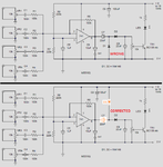
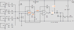
here i got a link with a circuit diagram for a 4 channel audio mixer using 741

https://wrojh.blogspot.in/2011/02/4-channel-audio-mixer-using-op-amp-741.html

4-Channel Audio Mixer Circuit.png

please check if it is ok or not . . should i implant it exactly ?
 

The 741 opamp design is 46 years old and is not suitable for audio because it is too noisy (hiss) and its low slew rate limits and distorts frequencies above 9kHz.
The polarity of C7 and D1 are wrong and D1 wrongly connects to ground instead of to the positive supply.

C7 and D1 and D2 and C8 cause distortion for the first pulse of music or speech because they short the output of the opamp when the capacitors charge.
Instead a second opamp should be used as a voltage doubler.

I have corrected it:
 

Attachments

  • audio mixer.png
    audio mixer.png
    38.5 KB · Views: 133

The 741 opamp design is 46 years old and is not suitable for audio because it is too noisy (hiss) and its low slew rate limits and distorts frequencies above 9kHz.
The polarity of C7 and D1 are wrong and D1 wrongly connects to ground instead of to the positive supply.

C7 and D1 and D2 and C8 cause distortion for the first pulse of music or speech because they short the output of the opamp when the capacitors charge.
Instead a second opamp should be used as a voltage doubler.

I have corrected it:


ya okkk well what would be the ckt configuration for the second stage ?
 

In addition to what audioguru said, there should be a current limiting resistor in series with the bc108 to prevent damage when the pot connected to it is turned all the way up. Anything from 1K to 10K should be OK.
 

I agree about the suggested buffer amplifier for the level indicator to avoid distortions. But I don't understand the "corrections" of the diode circuit.

I think the original rectifier circuit is just O.K., the diodes are connected correctly and C7 is always biased with the indicated polarity. If the OP output voltage swings rail-to-rail, C7 bias voltage drops to zero, but it gets never reverse biased.

The amplifier should be changed to TL07x.
 

I agree with FvM, with the 'corrected' diode polarity the transistor would conduct all the time. As the OP was looking for an audio mixer, I would omit all the circuitry after the op-amp altogether, it's only there to flash the LED on volume peaks. If it is left in place, I would add an isolating resistor in series with the cap feeding the voltage doubler so the op-amp wasnt just seeing diodes as it's load.

Brian.
 

I agree about the suggested buffer amplifier for the level indicator to avoid distortions. But I don't understand the "corrections" of the diode circuit.

I think the original rectifier circuit is just O.K., the diodes are connected correctly and C7 is always biased with the indicated polarity. If the OP output voltage swings rail-to-rail, C7 bias voltage drops to zero, but it gets never reverse biased.

The amplifier should be changed to TL07x.


well sir thats okk but what if i wish to use LA4440 in place of TL07x etc ?????????????????

- - - Updated - - -

Make your entire circuit like this:


hmm thats it . . okk surely i ll . .

- - - Updated - - -

well well well . . we don't need to concentrate on flash LED circuitry cause our issue deals with audio channel mixer & thats all we have to make sure about biasings

- - - Updated - - -

In addition to what audioguru said, there should be a current limiting resistor in series with the bc108 to prevent damage when the pot connected to it is turned all the way up. Anything from 1K to 10K should be OK.


hmm ya thats a point too . . thanks i ll remember that

- - - Updated - - -

Make your entire circuit like this:


so according to you which one is good if i replace 741 ??

In your diagram of 2 stage second one is 741 but 1st stage is mentioning an audio amp , so whats the ic number ?

- - - Updated - - -

Make your entire circuit like this:

Too from output of first stage a resistor you mentioned marked 100 before the capacitor followed by output

so is that 100 ohms ? right ?
 

well sir thats okk but what if i wish to use LA4440 in place of TL07x etc
LA4440 is an audio power amplifier module, so you talking about a quite different circuit. In case you plan to build a power amplifer with multiple input channels, it would still make sense to have a preamplifier, possibly also a tone control stage, according to your taste.
 

Since there are TWO diodes I corrected the circuit so it is a voltage doubler. D1 in the original circuit did nothing and the two capacitors divided the rectified voltage.
I agree that my "voltage doubler" does not work in this circuit.

Since you do not want the LED blink parts then why are they included in the original post??

A TL071 is a single low noise, low distortion, wide bandwidth audio opamp.
The resistor marked "100" is in ohms not in micro-Farads. It prevents the capacitance of an output cable from causing the audio opamp to oscillate at a high frequency.


why are they included in the original post??

that i too don't know because i just posted the original link & diagram as it is & i just want to deal with the part relating our aim

please tell any ic equivalent to TL071 or rather tell me any other number of it ?

- - - Updated - - -

LA4440 is an audio power amplifier module, so you talking about a quite different circuit. In case you plan to build a power amplifer with multiple input channels, it would still make sense to have a preamplifier, possibly also a tone control stage, according to your taste.


okk then tell something other than this for ic number sir
 

We could suggest many other OPs, e.g. LF356, LF353, MC4558, NE5532 or 5534, and hear again they aren't available at your place.

Alternatively you might ask your favourite electronic components shop for available low noise, audio bandwidth OPs and come again with the list.
 

We could suggest many other OPs, e.g. LF356, LF353, MC4558, NE5532 or 5534, and hear again they aren't available at your place.

Alternatively you might ask your favourite electronic components shop for available low noise, audio bandwidth OPs and come again with the list.


sir i got LF356 , MC4558 , NE 5534 . . so which of these you ll suggest if i ask you ?

- - - Updated - - -

Maybe there are not any audio opamps available in your country.
Here there are many available.


no its not like that actually i got LF356 , MC4558 , NE 5534 so suggest one for the circuit diagram you designed & posted above
 

The LF356 does not have its distortion spec'd so it is not a good single opamp for audio.
The old MC4558 is still available and is a fairly good dual audio opamp.
The NE5534 is a good single audio opamp.
 

LF356 would is clearly the best general purpose audio OP from the list. NE5534 can achieve lower noise, but only with low circuit impedances. It would perform rather bad in the post #1 circuit. MC4558 has more general purpose features, but still increased noise at 100k circuit impedance level.

P.S.: A detailed study about OP audio distortion says LF356 is slightly better than TL071. This according to my knowledge that it has been often used for audio applications.

https://www.sg-acoustics.ch/analogue_audio/ic_opamps/pdf/opamp_distortion.pdf
 
Last edited:

FvM, thank-you for the article about opamp distortion. I have never seen distortion results for the LF356 opamp before because it is not advertised to be an audio opamp like other audio opamps are.
 

Status
Not open for further replies.

Part and Inventory Search

Welcome to EDABoard.com

Sponsor

Back
Top