Continue to Site

Welcome to EDAboard.com

Welcome to our site! EDAboard.com is an international Electronics Discussion Forum focused on EDA software, circuits, schematics, books, theory, papers, asic, pld, 8051, DSP, Network, RF, Analog Design, PCB, Service Manuals... and a whole lot more! To participate you need to register. Registration is free. Click here to register now.

low voltage battery indicator circuit

Status
Not open for further replies.

Gaber2611

Member level 1
Joined
Apr 21, 2012
Messages
41
Helped
0
Reputation
0
Reaction score
0
Trophy points
1,286
Activity points
1,677
hello everybody,

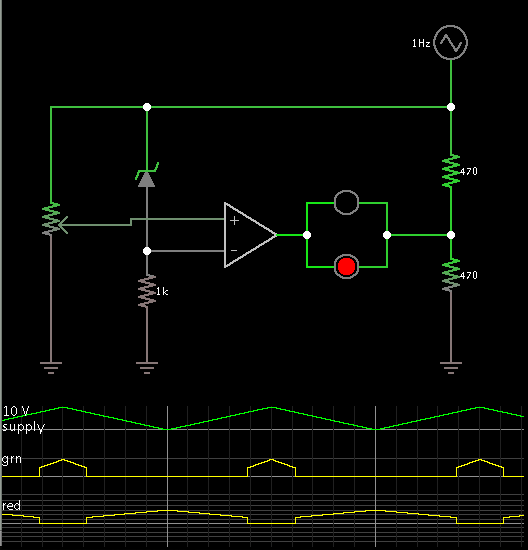
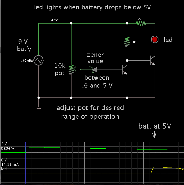
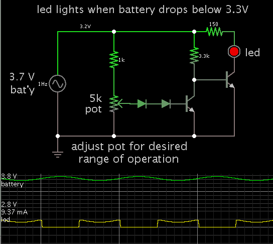
please i need a low voltage battery indicator, and the battery to be 9v, or 3v, to indicate a red led when the battery gets down under the 9v or the 3v, and please i need reliable circuit " one when make to work for sure", cause i got many from google and when simulated on proteus, never worked, so hope i get a serious help from anyone here

i prefer 555 circuits as it's common ic , so easy to get from markets here

Thanks in advance
 

You can design battery monitor using op-amp easily. What is your battery voltage? and type?
 

Forget the 555 it is completely useless for voltage monitoring.

It is easier to make the LED light up when the voltage is high enough and go out as the voltage drops but even then it's quite easy. Before explaining, you need to set some parameters. For example, it's no good saying the LED should light up when a 9V battery drops below 9V because it will light up almost straight away, you need to decide a lower voltage that you consider the 'danger' threshold when the warning should start. Maybe for a 9V battery it would be 8V. Also bear in mind that if the LED is also being powered from the same battery, it will not be able to light up if the voltage is too low anyway, this is particularly important it the voltage only starts at 3V because about half of that is needed to to power the LED.

Brian.
 

Thanks for the reply,

Samy, my battery voltage is 9v, Type is AAA battery, and which op-amp i should use?

Wixt: i understand that it will light the led when it's 8v, and no need to light when it's lower

my requirements is a schematic diagram which work for sure when connecting

another question: would it work for sure when it works on Proteus?, i mean when making the circuit for real, would it work when it's right working on proteus?

Thanks
 

How many levels if you want to monitor..

If only monitor the low battery use comparator with LM358 with zener reference.

It is simple way..
 

I'll describe the circuit, it's easier than drawing it.

Use an NPN small signal transistor, almost any type will work. Wire the LED and a 2.2K resistor in series beween the collector pin and the battery +.
Connect the emitter to the battery -.
Connect a 1M resistor between the base and emitter.
Connect a 4.7K resistor and a Zener diode in series between the base and battery +. The Zener voltage should be the 'trip voltage' - 0.6V, so for 8V you need 7.4V (use a 7.5V standard value).

The cathode (+) end of the Zener goes toward the battery positive.

The way it works is the battery voltage is dropped by the Zener voltage, if what's left is more then the Vbe of the transistor (about 0.6V), the transistor starts to conduct and lets current pass through the LED.

Brian.
 

i understand the circuit, and i know it's simple, but just nothing work when simulate it on proteus, does nyone here knows why?k, or can anyone draw such a simple circuit like this on proteus and capture and attach for me?
 

Hello there.

I'm searching for a low-voltage indicator LED aswell. but for a 18650 LiMn battery running at nominal 3.7V and I'd wish for the indicator-LED to light up at 3.3V.

My knowledge of electronics is down to read the partlist and the circuit and soldering the parts accordingly, I've got no understanding aboout calculating a circuit tho.

So my question would be, if it's not too much to ask, what the parts would need to be for a 3.7V battery with a threshold of 3.3V?
 

So my question would be, if it's not too much to ask, what the parts would need to be for a 3.7V battery with a threshold of 3.3V?

This should work:


The silicon diodes allow a more abrupt threshold of operation. They are not absolutely necessary.
 
  • Like
Reactions: bortre

    bortre

    Points: 2
    Helpful Answer Positive Rating
Much appreciated. Thanks very much :)
 

Brad,
Can your first circuit be modified to use a 2 pin bi-color LED, like Lumex SSL-LX25593, to show green when power is on and turn to red when low battery?
 

Brad,
Can your first circuit be modified to use a 2 pin bi-color LED, like Lumex SSL-LX25593, to show green when power is on and turn to red when low battery?

To use a 2-pin bicolor led, you want forward current flow sometimes, and reverse flow other times.

This will require more components. These will use up more of the battery's power.

Example, using an op amp as a comparator.


The op amp's supply leads are connected 'invisibly'.

The scope trace shows the green led lighting when the supply rises above 8V.

A zener diode with a value in the middle of the volt range will do. Adjust the potentiometer to obtain desired operation.
 

Thank you. That is almost exactly what I was looking at. Others have the zener diode and 1K resistor switched places. Does this matter?
 
Last edited:

Others have the zener diode and 1K resistor switched places. Does this matter?

Yes. A battery monitor is an oddball situation, where the supply voltage rises and falls. That is the signal applied to the inputs. We have four possible arrangements of zener and resistors. We must test which combination works correctly,

It will be the arrangement which causes a change in the output when the supply voltage rises (or falls) to a certain volt level.
 

Status
Not open for further replies.

Part and Inventory Search

Welcome to EDABoard.com

Sponsor

Back
Top