Continue to Site

Welcome to EDAboard.com

Welcome to our site! EDAboard.com is an international Electronics Discussion Forum focused on EDA software, circuits, schematics, books, theory, papers, asic, pld, 8051, DSP, Network, RF, Analog Design, PCB, Service Manuals... and a whole lot more! To participate you need to register. Registration is free. Click here to register now.

[SOLVED] Pwm out put through rc0 & rc1

Status
Not open for further replies.

m.naveed

Newbie level 6
Joined
Dec 16, 2012
Messages
13
Helped
2
Reputation
4
Reaction score
2
Trophy points
1,283
Location
lahore
Activity points
1,363
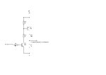
I'm confused after seeing a circuit with pwm signal for a 50Hz inverter which used RC0 & RC1 of P16F887.
RC1 is CCP2 out put its ok but how RC0 works same as RC1?
 

actualy Ii'm trying to work with ccp module of 16F887 and not well aware of it I seen a ups control card havin g the same MCu but it confused me as only one ccp module pin is used.
there are 2 same similar portions of circuit as shown in fig both drive a module conected to a center taped transformer to give ac out put.
I don,t hav e code but I knew its output i.e. 50Hz square wave with a 180 phase difrence as it is for a single phase Ac invert
 

Attachments

  • bising.jpg
    bising.jpg
    25.5 KB · Views: 96

Status
Not open for further replies.

Similar threads

Part and Inventory Search

Welcome to EDABoard.com

Sponsor

Back
Top