Continue to Site

Welcome to EDAboard.com

Welcome to our site! EDAboard.com is an international Electronics Discussion Forum focused on EDA software, circuits, schematics, books, theory, papers, asic, pld, 8051, DSP, Network, RF, Analog Design, PCB, Service Manuals... and a whole lot more! To participate you need to register. Registration is free. Click here to register now.

Help needed for determining lengths of coax and port cap for pyramidal horn antenna

Status
Not open for further replies.

Haziq Khan

Newbie level 5
Joined
Oct 26, 2013
Messages
10
Helped
1
Reputation
2
Reaction score
1
Trophy points
3
Activity points
66
I need help in determining the length of coax and portcap for pyramidal horn antenna.
I m using a SMA connector female 4 hole mount.
Inner diameter 1.3mm and outer diameter 4mm.
I m using HFSS.
 

Is the cable not impedance matched to the antenna? So are you looking to design the excitation pin then? I'm also not sure what a 'portcap' is. Does it have another name?

Yes i m designing the excitation pin. Cable will be matched at 50 ohms.
And i m also not sure what a port cap practically looks like. But i do know that it is placed above the wave port area. If it isn't their then HFSS gives the error of "Port refinement p1 bla bla bla".
 

Yes i m designing the excitation pin. Cable will be matched at 50 ohms.
And i m also not sure what a port cap practically looks like. But i do know that it is placed above the wave port area. If it isn't their then HFSS gives the error of "Port refinement p1 bla bla bla".

Here is my understanding of what you mean by Portcap.

In HFSS, internal excitations can only be set using lumped ports and not wave ports. So when using wave ports which is inside the solution box, it is advised to have one side of the wave port surface to be closed off by using a PEC cylinder. This is what is generally called as Portcap in most HFSS examples.

I suggest an alternative: You can draw a small cylinder behind your wave port and instead of assigning it as PEC, you can subtract it from your box. This way, your box will have a very small cavity (to which you assign radiation boundary conditions) inside it. I found this approach to be the same as having a portcap, while being less dependent on the size of the cylinder. Let the diameter and length of the cylinder be the same as the size of the wave port.

I understand what u r saying. But i am not fully confident how to apply it. Here is my design. If you have time plz have a look and modify it according to your understanding. Please and thanks in advance.
I m looking for a gain of 14 to 15 dB and return loss of -13dB or lower.
 

Attachments

  • Final_RL_GAIN_HMK_Finalll.rar
    44.9 KB · Views: 96

Also, if your coax cable is impedance matched, it doesn't matter how long it is, nor will its length affect the antenna's gain. If you are feeding your antenna via this coax, there is no need for this wave port to be internal.
 
Also, if your coax cable is impedance matched, it doesn't matter how long it is, nor will its length affect the antenna's gain. If you are feeding your antenna via this coax, there is no need for this wave port to be internal.

you mean i can get the coax long enough that it is outside the Air box and then i obviously dont need the port cap as it will be an external excitation... Right???
.
 

Yes, that's correct.

you mean i can get the coax long enough that it is outside the Air box and then i obviously dont need the port cap as it will be an external excitation... Right???
.
 
Also, if your coax cable is impedance matched, it doesn't matter how long it is, nor will its length affect the antenna's gain. If you are feeding your antenna via this coax, there is no need for this wave port to be internal.

Hey is it possible that i get my S11 by removing the virtual radiation box and treat the waveport as external (by cutting a circle in airbox) while i get my gain by using a port cap keeping the probe insdie both boxes.

In the above scenario obviously the probe position will be constant.
And i also want to knw if it works on HFSS thwn will it work practically. Cause i will also be fabricating this antenna.
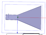
I have attached pics of both designs for the better understanding of wat i m trying to say.

cap1.PNGCapture.PNG

- - - Updated - - -

Here is my understanding of what you mean by Portcap.

In HFSS, internal excitations can only be set using lumped ports and not wave ports. So when using wave ports which is inside the solution box, it is advised to have one side of the wave port surface to be closed off by using a PEC cylinder. This is what is generally called as Portcap in most HFSS examples.

I suggest an alternative: You can draw a small cylinder behind your wave port and instead of assigning it as PEC, you can subtract it from your box. This way, your box will have a very small cavity (to which you assign radiation boundary conditions) inside it. I found this approach to be the same as having a portcap, while being less dependent on the size of the cylinder. Let the diameter and length of the cylinder be the same as the size of the wave port.

Hey is it possible that i get my S11 by removing the virtual radiation box and treat the waveport as external (by cutting a circle in airbox) while i get my gain by using a port cap keeping the probe insdie both boxes.

In the above scenario obviously the probe position will be constant.
And i also want to knw if it works on HFSS thwn will it work practically. Cause i will also be fabricating this antenna.
I have attached pics of both designs for the better understanding of wat i m trying to say.
cap1.PNGCapture.PNG
 

Status
Not open for further replies.

Part and Inventory Search

Welcome to EDABoard.com

Sponsor

Back
Top