Continue to Site

Welcome to EDAboard.com

Welcome to our site! EDAboard.com is an international Electronics Discussion Forum focused on EDA software, circuits, schematics, books, theory, papers, asic, pld, 8051, DSP, Network, RF, Analog Design, PCB, Service Manuals... and a whole lot more! To participate you need to register. Registration is free. Click here to register now.

[SOLVED] Choosing transistors for current mirrors?

Status
Not open for further replies.

Darkcobra

Member level 3
Joined
Nov 20, 2010
Messages
55
Helped
13
Reputation
28
Reaction score
14
Trophy points
1,288
Activity points
1,883
The actual current output of a simple two-transistor bipolar current mirror changes with the voltage at the output terminal. I'm trying to reduce this without using a higher part count mirror (no Wilson, Widlar, etc).

I've tried with the transistors on hand, the 2222/2907 and 3904/3906. The latter performed much better, but not as well as I'd like, and I think there must be better transistors for the task. My questions:

1) What spec(s) should I compare in a datasheet that would indicate how well a transistor will work for this purpose?

2) Finding a transistor with the desired specs out of the thousands available is a bit overwhelming. Though I can filter by various specs on some vendor sites, this tells me nothing about how common the parts are; and I'd like to limit my designs to the most common and widely available types as much as possible (for the United States). I've searched for "common transistors", but generally find only the 2222/2907 and 3904/3906 that I already have mentioned. I'd like to find others, and if there's a "top ten" list out there somewhere, that would be perfect. Does such a thing exist? Failing that,

3) Can you recommend a common and widely available transistor that would perform better than 3904/3906, preferably available in both TO-92 and SMD?


I doubt the transistor parameter you need will be specified in the data sheets so it is probably simpler to just add a transistor and eliminate the effect. A well matched transistor pair won't help with the variation in output current with output voltage anyway.

Keith
 

The actual current output of a simple two-transistor bipolar current mirror changes with the voltage at the output terminal. I'm trying to reduce this without using a higher part count mirror (no Wilson, Widlar, etc).

I've tried with the transistors on hand, the 2222/2907 and 3904/3906. The latter performed much better, but not as well as I'd like

I only need to reduce fluctuations of output current into a rapidly changing load.

I assume that output capacitance is the parameter that makes the difference between 2N2222 and 2N3906. 2N2222 has larger chip area and about double the capacitance. Low frequency output resistance should be almost equal.
 
I think I may have a theory. First, I found one additional recommendation for a common transistor - the 2N4401/2N4403. I don't have those, but I ran a comparative test in SPICE to see which would produce the most stable 10mA, with a simulated signal generator at the output terminal swinging nearly rail-to-rail. Then I looked at datasheets to find any parameters (at least those I understand) that seemed to be a predictor of stability.

I take SPICE results with a grain of salt, but it did not appear to be output capacitance as FvM suggested; instead I found another correlation:

2N2907: 10-20mA fluctuation, Co=8.0pF, hFE@10mA=110
2N3906: 10-15mA fluctuation, Co=4.5pF, hFE@10mA=140
2N4403: 10-11mA fluctuation, Co=8.5pF, hFE@10mA=240

Seems to be related to hFE, in particular at the current of interest. But I'm more a digital guy. So if anyone can verify this, it would be appreciated!
 

For a meaningful discussion, can you please add a few words about your specification of "current fluctuations"?

My assumption that it's an output capcitance related problem was triggered by the keywords "rapidly changing load". But in fact that's a non-specification without a time scale. Now you're talking about rail-to-rail swing which might indicate saturation problems.

To clarify things, please show test circuit and waveforms.

A word of caution. Although the gummel-poon transistor model used in SPICE simulation is pretty good, it's not said that models for particular transistors are including all parameters relevant for your problem. And if one model does, it's not necessary the case for another one.
 
The actual current output of a simple two-transistor bipolar current mirror changes with the voltage at the output terminal.
That's due to Early effect.

1) What spec(s) should I compare in a datasheet that would indicate how well a transistor will work for this purpose?
You want transistors with a large "Early voltage". Unfortunately, that's not normally shown on datasheets.
Where h-parameters are given, you could use hoe (output admittance) or hox (output impedance).


Apparently, KSC3503 & KSA1381 are very good in this respect, but are TO126.
From Edmond Stuart at diyAudio.com:
In fact, KSC3503 & KSA1381 are small signal transistors in a medium-power package, targeted at high definition CRT video output stages. So they do have a high ft and low Cob. Moreover, they have an exceptional high Early voltage.
.... real Early voltage of a KSA1381-E is about 400V (@ Ic = 5 ... 15mA)
.....real Early voltage of a KSC3503-D is about 700V.
 
Last edited:
To clarify things, please show test circuit and waveforms.

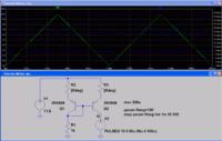
Sure. The test circuit I used:


Function generator XFG1 outputs a triangle wave at 10khz, from 0-10V, to simulate the changing voltage the current mirror will see at its output terminal. I am aware in that this synthetic test, the mirror will saturate (if that's the correct term) near 10V, and that's something I will design a real circuit to avoid or tolerate. But I do have a few circuits where I do want to swing as close to the rails as possible, and that's why I'm trying to make this method work better; rather than using a Wilson mirror, current limiting diode, etc.

Here's the waveforms for the 2N4403, the best of the three I tried. The voltage trace for XFG1 is shifted down (not inverted) so that it doesn't overlap the other trace, for clarity's sake. The current trace includes the spikes as a result of saturation, ignore those:


Quite acceptable. Here's the 2N3906, which is worse:


And the 2N2907. This is what I originally used, and the unacceptable performance is what caused me to start investigating this:


I understand your caution against taking SPICE results too literally. But if I can at least use it to figure out which transistor specification generally predicts stability, then I can at least make some educated guesses on some new transistors to add to my next order, and perform real-world tests on.

If you need additional info, let me know. I very much appreciate the help.
 

The "fluctuations" in the current test are rule by statical output resistance (respectively Early voltage) and partly by transistor saturation.

- There is an obvious saturation problem. For reasonable results, keep a few 100 mV residual Vce voltage.
- Your 2N2907 and 2N3906 output waveforms indicate unrealistic model parameters, or circuit errors. Check parameter VAF. Realistic values for small signal transistors are in a 50 - 120 range.

You can considerably improve CM output impedance by emitter degeneration resistors, as shown in the below parametric simulation with 0, 10 and 100 ohm. (With free LTSpice, simulation file attached.)


Attachments

  • Current Mirror.zip
    830 bytes · Views: 111
That's due to Early effect.
You want transistors with a large "Early voltage". Unfortunately, that's not normally shown on datasheets.

Interesting, I've never heard of that. The link gave a good description, and it sounded feasible. So I looked up the Early Voltage (Vaf) parameter in my SPICE models:

2N2907=10
2N3906=18.7
2N4403=115.7

These numbers do in fact predict, with what appears to be perfect linearity, how stable a simulated current mirror using these parts is. I'm fairly confident you've nailed it!

But I definitely question the accuracy of the Vaf in those models. I tried looking up actual Vaf for those parts, and got numbers all over the place, with little agreement. None suggested a 2N2222 would have a Vaf anywhere near as low as 10, though. I also found this:


Which I may be able to wrap my head around later. And one more useful thing:

"More significantly, the MPSA92 had outstandingly high output impedance; a/k/a enormous Early voltage."

That source didn't say exactly what the voltage was, but I found another reputable reference that it's 260, which I think is good enough for me. And it's in TO-92 (or SOT-23, MMBTA92). Plus I believe I actually have some of these on hand to do some real-world tests on. A shame its complement (MPSA42) has only 45.1, I'll have to keep looking there.

Thank you!

- - - Updated - - -

Your 2N2907 and 2N3906 output waveforms indicate unrealistic model parameters, or circuit errors. Check parameter VAF. Realistic values for small signal transistors are in a 50 - 120 range.

Looks like we're all in consensus as Vaf being the issue, so I'm going to mark this solved.

You can considerably improve CM output impedance by emitter degeneration resistors, as shown in the below parametric simulation with 0, 10 and 100 ohm. (With free LTSpice, simulation file attached.)

I'll give that a try as well. Thank you!
 

2N2907=10
2N3906=18.7
No idea how they derived these numbers.

I can't say, if MPSA92 has higher Early voltage than standard small signal transistors. If so, you would be completely misleaded if you trust the SPICE model provided by Onsemi. It tells a VAF value of 10.

What probably happens is this: SPICE models are often automatically generated based on datasheet specifications. If the datasheet has no or at least no typical specification for a particular parameter (in this case output admittance h22e), arbitrary default or worst case parameters might be put in.
 
I can't say, if MPSA92 has higher Early voltage than standard small signal transistors. If so, you would be completely misleaded if you trust the SPICE model provided by Onsemi. It tells a VAF value of 10.

You're right, I was completely misled by this. I'm continuing to look up info and have seen a few recommendations at this point that if unknown, the default Vaf for standard small signal transistors should be set in the 50-100 range. 10 seems unrealistically low.

The Vaf's I quoted for MPSA92/MPSA42 came from the "Audio Power Amplifier Design Handbook" by Douglas Self. I know he has the capability to measure that directly, though I'm not sure whether he did so in this case. At any rate I'll consider sources like these more trustworthy than OnSemi's Vaf of 10.
 

I don't know why you persist in avoiding a circuit topology with guaranteed success regardless of transistor parameters in favour of trying to hunt down transistors with an uncontrolled, badly specified parameter in the hope it will work. I would just use a decent current mirror design and be done with it.

Keith
 

I don't know why you persist in avoiding a circuit topology with guaranteed success regardless of transistor parameters in favour of trying to hunt down transistors with an uncontrolled, badly specified parameter in the hope it will work. I would just use a decent current mirror design and be done with it.

I already mentioned I'm better at digital (software actually) than analog.

Therefore, I'm currently trying to fully understand and improve this particular circuit, the two-transistor current mirror. That's why I clearly stated I had no interest in other topologies in the first paragraph of my first post, along with specifically naming a few to demonstrate I'm already familiar with their existence and properties. Discussion or recommendations of other topologies, while I'm sure they're intended to be helpful, may have the opposite effect - as they may lead someone quickly scanning the thread to think my question has been answered, when it has not.

Once I've accomplished that (and I think thanks to the help here I've succeeded), I plan to build a number of generic current mirror modules, which can be plugged into a breadboard to assist in rapid prototyping and testing of larger circuits in the real world. I intend to post this and other designs on an upcoming website, along with theory of operation, limitations, and challenges/pitfalls encountered along the way; which may be helpful to others coming from my background.

I understand that building the "perfect" current mirror is impossible, some tradeoffs must always be made. In this case, I believe a current mirror that has slightly imperfect regulation is more generic and less limiting, than one that cannot drive outputs as close to the rail. Because in a quick (and possibly naive) modular prototype, a few percent error in current regulation will probably be tolerable; but if the voltage limitations of successive modules add up to too much, that's guaranteed failure rather than the guaranteed success you claim.

This does not preclude me from also making a separate three-transistor mirror module to be used where more appropriate. Or optimizing a final design, rather than using generic modules. But that's beyond the intended scope of this thread.

My reference to several audiophile resources is only because that's where I've been able to find relevant information. I have no interest in building high quality audio amps, other than perhaps as an educational exercise.

Does that explain it?
 

I'd have to say I'm very interested in your 'educational exercise'. I would like to see your results if you dont mind.
 

I'm currently trying to fully understand
and improve this particular circuit, the two-
transistor current mirror


You are simply trying to select a different transistor which has a higher early voltage. That is not "improving" the circuit. The improvements in the basic current mirror circuit were developed many years ago and are the different topologies mentioned. Also, don't forget matching issues.

The cause of the less than infinite resistance of a current mirror should have been explained in the books where you read about the other current mirror designs. That, and the elimination of base current errors, is the reason for the different designs although without well matched devices it would seem irrelevant to try to eliminate base current errors.

Keith
 

My reference to several audiophile resources is only because that's where I've been able to find relevant information.
Indeed. Here's a couple more:

Bob Cordell's made SPICE models of a number of transistors, based on actual measurements. You can download them for free from his website here. They should be a lot more accurate than the models provided by manufacturers. BTW, he's the author of "Designing Audio Power Amplifiers" - another fine book you're probably not interested in. :p

Greg Erskine's put together lists of popular transistors (with their basic parameters) to make part selection easier. It's on his website here. There's links at the top of the page for medium and high power transistors.

P.S. One slight issue with Bob's SPICE models: he added "C" to the end of each part number to distinguish his models from the others in your library. IMO, that wasn't too well thought out as a number of parts use alphabetic suffixes anyway, to indicate e.g. gain group. Anyway, I just edited my copy of the library and added the prefix "bob" to all the part numbers to make the distinction more stupid-proof.
 
Last edited:
Bob Cordell's made SPICE models of a number of transistors, based on actual measurements.
Greg Erskine's put together lists of popular transistors (with their basic parameters) to make part selection easier.

That is a treasure trove, and will be very helpful to me. Thank you!

I'd have to say I'm very interested in your 'educational exercise'. I would like to see your results if you dont mind.

If you're referring to the audio amp, I'm not sure it would be particularly useful to anyone but me. It's designed from scratch, using no other completed design as a starting point or inspiration, and exists only in SPICE. Each time I learn something new and significant about how a part or basic circuit block works, I go back and see if I can improve it. I have not taken quantitative measurements for THD and such, and I'm sure it's nothing special.

Plus I realize I'll never build and use it as a standard audio amp, as IC amps are cheap, everywhere, and good enough for my tin ear. But I may have future need for something I cannot easily buy, an amp for driving unusual loads; for example those with significant capacitive components that might send a normal amp into oscillation. So the most current revisions were optimized for that, rather than maximum fidelity into a standard speaker.

If you're still interested, I'll clean up the current schematic and post it.

You are simply trying to select a different transistor which has a higher early voltage. That is not "improving" the circuit.

I could say "tuning", "tweaking", or whatever. But you understood what I meant. I'm disappointed to see that my detailed explanation I took the time to write - at your request - goes unacknowledged except for nitpicking a single term.

The cause of the less than infinite resistance of a current mirror should have been explained in the books where you read about the other current mirror designs.

Perhaps we learn from different resources, or in a different way. I quickly get lost when a document makes the transition from plain English descriptions, to a series of formulas and excessive jargon. Instead, I learn mostly by experimenting. Once I've witnessed any particular behavior and know its name, then I have a reference point to go back, reread, and fully understand a particular technical aspect. Maybe you consider that odd. But I am doing my best, and when I rarely have to resort to asking for help on a forum that exists for that purpose, being told by a moderator that "you should have learned that from a book" is also disappointing.
 

NXP Matched pair transistors intended for current mirrors **broken link removed** has under Dicumentation SPICE models and you can compare them with others.
 

Status
Not open for further replies.

Similar threads

Part and Inventory Search

Welcome to EDABoard.com

Sponsor

Back
Top