juz_ad
Full Member level 2
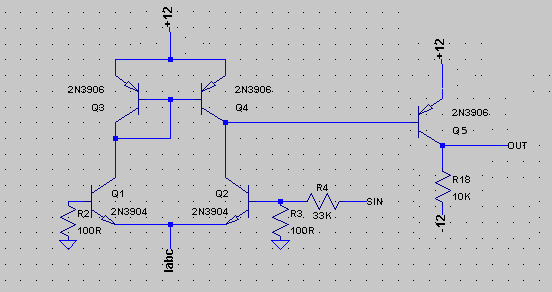
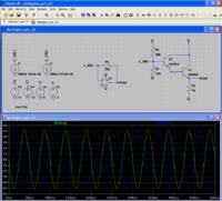
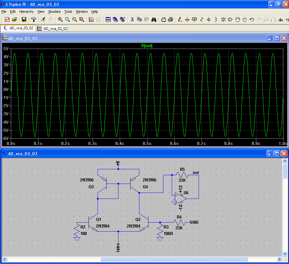
I have an OTA with an op-amp I-V converter giving output at unity gain on a 20Hz +/- 5V sine wave input. It works fine, basic circuit is below:
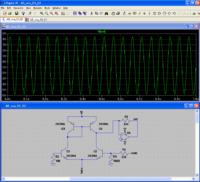
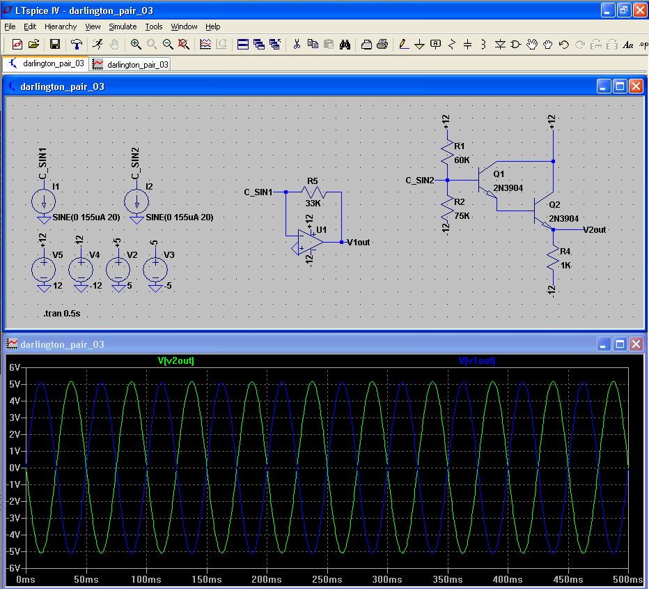
I wanted to swap the op amp I-V converter for a transistor output - so I simulated a darlington pair in isolation and was able to reproduce the same output as the I-V converter (although the darlington is inverted - which is fine).
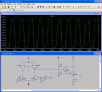
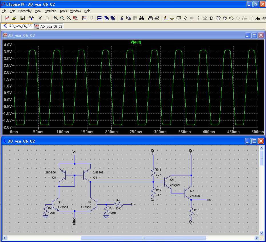
When I added the darlington pair to the original OTA - you can see the output is lower amplitude, clipping and doesn't want to swing below approx. -2V - regardless of the bias R values.
[Edit: with values for R17 < approx. 5K the output will swing below -2V but I'm still losing the gain. Thanks.]
Can anyone suggest a possible cause and solution to this? Thanks!
I wanted to swap the op amp I-V converter for a transistor output - so I simulated a darlington pair in isolation and was able to reproduce the same output as the I-V converter (although the darlington is inverted - which is fine).
When I added the darlington pair to the original OTA - you can see the output is lower amplitude, clipping and doesn't want to swing below approx. -2V - regardless of the bias R values.
[Edit: with values for R17 < approx. 5K the output will swing below -2V but I'm still losing the gain. Thanks.]
Can anyone suggest a possible cause and solution to this? Thanks!
Last edited: