Continue to Site

Welcome to EDAboard.com

Welcome to our site! EDAboard.com is an international Electronics Discussion Forum focused on EDA software, circuits, schematics, books, theory, papers, asic, pld, 8051, DSP, Network, RF, Analog Design, PCB, Service Manuals... and a whole lot more! To participate you need to register. Registration is free. Click here to register now.

Reduce Power Consumbtion in DC/DC Boost converter

Status
Not open for further replies.

alzomor

Advanced Member level 2
Joined
Jun 9, 2005
Messages
674
Helped
39
Reputation
78
Reaction score
8
Trophy points
1,298
Location
Germany
Activity points
6,406
Hi,

I need to drive 5mAmps in a load up to 20Kohm from 9V resistor.
In order to do so I made a boost converter to boost the 9V up to 120V.
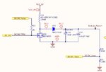
Boost.jpg
The pulse driving the MOSFET 140 micro second and the duty is 14 micro second
this was the max current in the coil = 9*14/120 = 1.05 Amp
and the average current consumed by the circuit without load = (0.5 * 1.05 * 14)/140 =52.5mAmps which is so much.

Is there any way to reduce the current consumed in the mosfet while keeping the switching frequency low to avoid EMC problems.

Regards
Hossam Alzomor
 

If the mosfet is turned on at any frequency, it is going to draw current. That is the function of the first half of a boost converter cycle.

The only way to prevent current consumption... is to avoid turning on the mosfet.
 

If you want 5mA into 20k that is 0.5W. So 100% efficiency would require 0.5W from your 9V supply = 56mA. You cannot do better than that.

Keith
 

thanks Brad & Keith,

The problem is that this current is consumed at no load
in other words the output of boos converter is not driving a load.
I under stand that the current should be 56mA or more when driving the 5mA in 20K load , but why it's 56mA when there's no load or when the current is less than 5mA or when the load is less than 20Kohm?

Regards
Hossam Alzomor
 

Ideally, there's no current consumed without load and the primary duty cycle approaches zero. For actual current consumption, you have to consider transistor switching speed, transistor and inductor losses.

I can't recognize a correct calculation in post #1.
 

FvM,

May you kindly let me know what's wrong in the calculations?
 

The error in reasoning is to assume a fixed ton respectively duty cycle. The duty cycle has to be adjusted by a feedback circuit according to the load.

With the assumed fixed duty cycle (and a lossless converter) you would get about 100 V into 20 k load and infinite output voltage into no load.
 

in simulations the output voltage ramps up to about 118volts in about 500mSec and starts saturation after that
it saturates at about 120V
this simulations is done without load
Practical measurements show similar results
 

in simulations the output voltage ramps up to about 118volts in about 500mSec and starts saturation after that
it saturates at about 120V
this simulations is done without load
Practical measurements show similar results
I believe that's the case, because IRF540 has maximum Vds rating of 100V. It will clamp overvoltages according to the avalanche specification. In steady state, most of the input power gets burned in the MOSFET.

In a reasonably designed circuit, the MOSFET has sufficient voltage rating and the duty cycle will be reduced at 120V output. For simple applications, on/off control might be suitable.
 

but the peak reverse voltage for the diode BAS521l is 325v so the 100 volts will not be applied on the IRF540N Mosfet
 

Both components have to stand 120V. Consider boost converter operation.
 

Status
Not open for further replies.

Similar threads

Part and Inventory Search

Welcome to EDABoard.com

Sponsor

Back
Top