Continue to Site

Welcome to EDAboard.com

Welcome to our site! EDAboard.com is an international Electronics Discussion Forum focused on EDA software, circuits, schematics, books, theory, papers, asic, pld, 8051, DSP, Network, RF, Analog Design, PCB, Service Manuals... and a whole lot more! To participate you need to register. Registration is free. Click here to register now.

Help with Hall effect sensor in DC-AC Converter

Status
Not open for further replies.

jean12

Advanced Member level 2
Joined
Aug 27, 2013
Messages
529
Helped
5
Reputation
12
Reaction score
6
Trophy points
18
Activity points
5,497
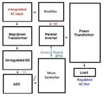
Hello there,I am designing a dc-ac converter and I want at a high load to maintain the output voltage 220VAC,for that I want to use Hall effect sennsor for sensing the current so interface this to a PIC,can anyone give further ideas for better development?

Thanks.
 

It's not clear why you would use a hall effect sensor in your design. Output voltage will be primarly kept constant by a voltage control loop. In case you want to use some kind of current feedforward, it could use a current transformer as the output is AC.

But if you want a hall effect sensor for some reason, it's output can be interfaced to a microprocessor like any other analog quantity, e.g a voltage measurement. There's nothing special about it.
 

I am reapiring a dc/ac converter which were using a hall effect at the AC output and what it reads goes back to the board I think to a microcontroller,but for the moment the converter works for 2 minutes and stops and the error which has made the converter out of use is that an unexperienced person has connected the output of the converter to a generator and all two (converter and generator were operating) from that time the Conveter works for 2 minutes then it stops I am thinking that the input to that microcotroller from the hall sensor has had some problems.


Please help,thanks.
 

Use a 10k pull-up resistor between power and output (usually from pin 3) to get a clear on/off state.
 

Your quoting an error message, but any information about the hall sensor type, circuit, expected versus actual signal is missing.
 

Dear vicky001.iith ,where are you saying that I have to add a pull-up resistor,it is on pin 3 of what??

Please help
 

I have recently worked on an AC Voltage Stabilizer that is using a double conversion topology.
The AC Mains is converted to DC and is again inverted back using a parallel inverter. Then the effective output is changed by varying the width of the PWM Pulses.
But our design is currently performing only line regulation.

Since you are performing DC-AC conversion and require a stable output at the conversion end, I suggest you take a voltage feedback back from the output of the inverter.
This can be done by stepping down the voltage, converting in to DC, filtering it and leaving it unregulated...
By doing so, you will be performing load regulation and i think it is easier to take a simple voltage feedback than interfacing a hall effect sensor with the PIC.

I'll attach the B.D of our design. Hope it helps you to understand my explanation in a better way.

P.S : I have not drawn the comparators in the B.D. They will be comparing the unregulated DC out with a preset level. The output of the comparator will be fed into the PIC which will then control the duty cycle of PWM.
 

Attachments

  • final.jpg
    final.jpg
    39.1 KB · Views: 104

Hello,for a MOSFET controlled by a square wavehow much the voltage controlling the Gate must be so that the MOSFET can go in ON mode.(in operation).

I did this with a PIC16F876A and established a dead time for command but I am not succeeding,can anyone help me?
See the codes and circuit;see also the codes I used:
PHP:
#include "16f876A.h"
#device ADC=8
#fuses  NOWDT,HS,NODEBUG,NOCPD
#use delay(clock=12M)

void main()
{

set_tris_b(0x00);
//output_b(0x00);

while(1)
{

   output_high(PIN_B4);
   output_low(PIN_B5);
   delay_us(30);
   
   output_low(PIN_B4);
   output_low(PIN_B5);
   delay_us(3);


   output_low(PIN_B4);
   output_high(PIN_B5);
   delay_us(30);


   output_low(PIN_B4);
   output_low(PIN_B5);
   delay_us(3);
}
   
   
   }

Please Help.
 

Attachments

  • crtt.zip
    13.1 KB · Views: 91

but I am not succeeding
Which particular problem do you observe?

The most obvious problem is that IRF640 can't be fully turned on by 5V gate voltage. PIC output ports also aren't made to drive the high gate capacitance. Use a driver IC like TC427.

The delays should be adjusted for 30 kHz.

Related to the original question, the post is completely off-topic.
 

Status
Not open for further replies.

Similar threads

Part and Inventory Search

Welcome to EDABoard.com

Sponsor

Back
Top