Continue to Site

Welcome to EDAboard.com

Welcome to our site! EDAboard.com is an international Electronics Discussion Forum focused on EDA software, circuits, schematics, books, theory, papers, asic, pld, 8051, DSP, Network, RF, Analog Design, PCB, Service Manuals... and a whole lot more! To participate you need to register. Registration is free. Click here to register now.

IR2110 working 90% some distortion at GATE HELPPP

Status
Not open for further replies.

Electronics_chaitanya

Member level 5
Joined
Oct 27, 2010
Messages
91
Helped
7
Reputation
14
Reaction score
5
Trophy points
1,288
Location
India
Activity points
1,985
on load.jpgno load.jpgHello friends


After struggling for some days i successfully made gate driver suing IR2110.Giving nice HO and LO but i face some distortion as shown in fig below so please help me to reject it....


**broken link removed**


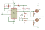
Here you can see some distortion circuit i am using is attached.

I am not placing diodes across gate resistance because it increase distortion more.

I hope you good peoples will help me
 

Attachments

  • IR2110 - 2.png
    IR2110 - 2.png
    44.9 KB · Views: 114

Hello


Thanks for your replay after putting capacitors i get improvement in output but output is not 100% pure .....Is this occur due to PCB fault??? at ths time i am using general purpose board not pcb........ plz help
 

What is it that bothers you? The over and undershoot? That would partially be because of the poor return path (ie your breadboard). Its also because it is an unmatched translission line. You can dampen those effects by keeping the line short. Another solution is to add a series resistor but that will increase switching losses.
 

By taking output is not 100%, how high is that?
What do you mean output (it is output of IC or FODFET gate pin)?

Hello


Thanks for your replay after putting capacitors i get improvement in output but output is not 100% pure .....Is this occur due to PCB fault??? at ths time i am using general purpose board not pcb........ plz help
 

Hello

Output means signal at gate of mosfet...i am not considring actual output of whole circuit......


Another problem is that when my load current is about 3 to 4 A circuit works ok but when current increas to 10A it burns mosfets.....i am usinh irfp250.....which is capable to handle much larger current
 

No no i am applying only 30v instead of 300v shown in fig....


I am using 15KHz frequency...... but no idea about dead time.....can u tell me how do i know about dead time?? I am using sg3525
 

Status
Not open for further replies.

Similar threads

Part and Inventory Search

Welcome to EDABoard.com

Sponsor

Back
Top