Continue to Site

Welcome to EDAboard.com

Welcome to our site! EDAboard.com is an international Electronics Discussion Forum focused on EDA software, circuits, schematics, books, theory, papers, asic, pld, 8051, DSP, Network, RF, Analog Design, PCB, Service Manuals... and a whole lot more! To participate you need to register. Registration is free. Click here to register now.

Stereo line to mono convertor using simple configuration

Status
Not open for further replies.

rajaram04

Advanced Member level 3
Joined
Jun 17, 2012
Messages
871
Helped
6
Reputation
12
Reaction score
5
Trophy points
1,298
Location
earth
Activity points
7,687
Hello sir

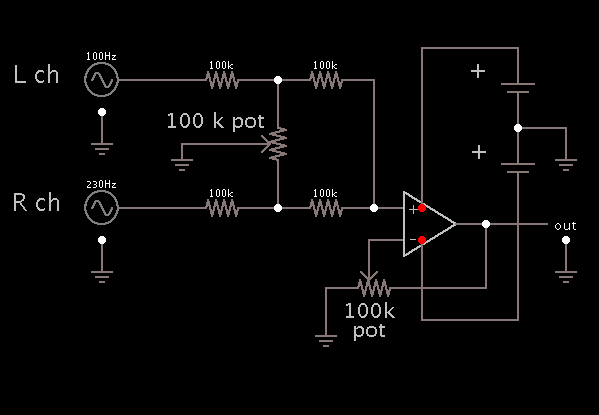
Sometimes in live shows we need to play stereo out instruments with a mono line as we don't always get such hifi PA system so we have to manage with them . . . . If i connect my left channel to output i am unable to hear right one at out end or vice verca , so i need a proper ciruit diagram for stereo to mono convertion with simple available components no matter its transistorized or with ICs . . please help . . thanks
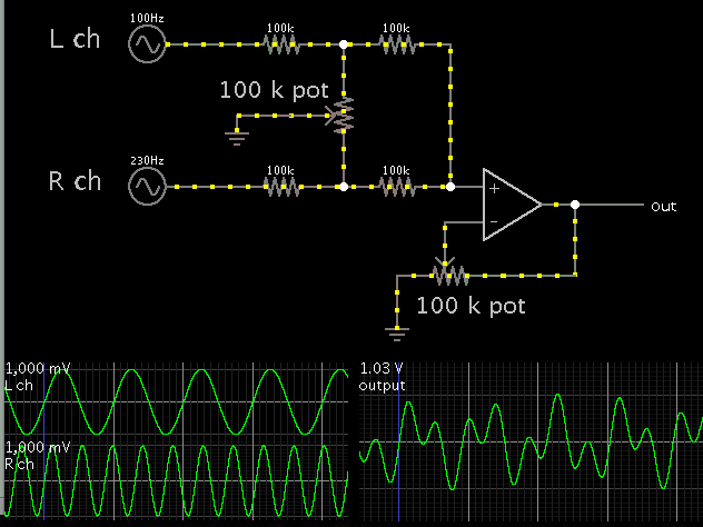
 

Since you want to monitor L and R channels separately before the point where they are mixed, then you want to maintain high impedance between them.

You can use an op amp in mixer configuration. Put high-ohm resistors at the inputs. The op amp should have a high impedance.


The pot across the inputs is a simple L-R balance control.

The other pot adjusts gain. Since the sum of two channels can raise volume by 6 dB, you probably will want to reduce gain.


wow thats look like a best one :) thanks sir . . well which op amp should i implant ? please specify a good one . . is 741 ok or anything else like 810 etc ?
 

A 741 opamp is 45 years old and was not designed for audio because it has too much hiss and has trouble above only 9kHz.
A TL071 is a good single audio opamp that has low noise and works well up to 100kHz.
 

Op amp with Low THD, Low noise and high slew rate are good for audio applications. Op amp TL071 and TL072 are using generally for audio amplifiers for more than a decade. LT1115 is the best choice for audio amplifiers.
 

woww thats a great idea . . thanks & hoping for the best . . let me applt this first
 

A 741 opamp is 45 years old and was not designed for audio because it has too much hiss and has trouble above only 9kHz.
A TL071 is a good single audio opamp that has low noise and works well up to 100kHz.


in place of TL071 which one of these suits better here ???

LF356 , MC4558 , NE5534
 

I answered on your other thread.
The LF356 does not have its distortion spec'd so it is not a good opamp for audio.
The MC4558 is pretty old but is still available. It is a fairly good dual audio opamp.
The NE5534 is a good audio opamp.
 

Since you want to monitor L and R channels separately before the point where they are mixed, then you want to maintain high impedance between them.

You can use an op amp in mixer configuration. Put high-ohm resistors at the inputs. The op amp should have a high impedance.


The pot across the inputs is a simple L-R balance control.

The other pot adjusts gain. Since the sum of two channels can raise volume by 6 dB, you probably will want to reduce gain.


sir this one is not working anyway , i applied LF356 as audio ic . . what to do now
 

Did you connect a + and - Power Supply to the IC?

If you did the Circuit Should work.
 
Last edited:

As Chemelec states, the op amp needs a bipolar supply. The input and output signals are referenced to ground, at the node between the + and - supplies.

Question: Is the L or R channel riding a DC component? Then you may need a blocking capacitor somewhere.
 

Did you connect a + and - Power Supply to the IC?

If you did the Circuit Should work.


hmm yo i did everything completely but . . . .

- - - Updated - - -

As Chemelec states, the op amp needs a bipolar supply. The input and output signals are referenced to ground, at the node between the + and - supplies.

Question: Is the L or R channel riding a DC component? Then you may need a blocking capacitor somewhere.


hm ok then what about the proper circuit digram & configurations ?

what is chemelec state ?

no its not riding dc component its simple analog out from an amplifier or a sound card
 
Last edited:

hm ok then what about the proper circuit digram & configurations ?

what is chemelec state ?

no its not riding dc component its simple analog out from an amplifier or a sound card

Here is a schematic showing connections for the bipolar power supply and ground.

It shows ground icons close to their associated wires, where you would hook up L-R input and output.

It shows power leads going to the op amp, similar to typical diagrams. (I had to draw artificial power leads to the op amp. Falstad's simulator omits them to keep it simple.)


hmm yo i connected in that manner but not a single result i am getting from that , i raised the volume fo each connected device to its "full" but . . . . .
 

Did you try a two resistors (e.g. 10 k) as simple signal mixer? Fits easily into a stereo-to-mono adapter cable.
 

Did you try a two resistors (e.g. 10 k) as simple signal mixer? Fits easily into a stereo-to-mono adapter cable.


hm ya i applied tw0 4.7k resistor as passive network . .

bot L & R are connected to same line via 4.7k in series just as available on net

that one is working very fine but actually i want to design it with some active circuit arrangments
 

hmm yo i connected in that manner but not a single result i am getting from that , i raised the volume fo each connected device to its "full" but . . . . .

To gain any success, you will need to get the op amp working as a basic amplifier (or in any way you can persuade it).

Do you get any sound from the output? Any hiss or hum or buzz?

Try touching your finger to the input terminals on the IC. (Touch an earth ground first, to drain any static charge.)
Any hum or buzz?

Apply a DC voltage to the input terminals. A DC voltage should appear at the output.

Or else, substitute a different IC. Etc.
 

that one is working very fine but actually i want to design it with some active circuit arrangments
O.K. in lack of anything better to do...
 

To gain any success, you will need to get the op amp working as a basic amplifier (or in any way you can persuade it).

Do you get any sound from the output? Any hiss or hum or buzz?

Try touching your finger to the input terminals on the IC. (Touch an earth ground first, to drain any static charge.)
Any hum or buzz?

Apply a DC voltage to the input terminals. A DC voltage should appear at the output.

Or else, substitute a different IC. Etc.


hm i applied everything u told , firstly no humm or hiss is there , secondly when i touch input 2 i get a distorted sound like as we usually hear while touching a grid , . . now i guess this 100k is obstacle may be but not sure . .
Last year i did several experiments on amps preamps etc depending on explanations discussed in this forum , all done , but don't know why this one is not . . may be first i ve to make simple audio amp function for the selected IC . . is there any good diagram for audio amp using LF356 ??????

- - - Updated - - -

O.K. in lack of anything better to do...


i applied it sir as shows are from 11th to 14th dec continue & i ve to edit so many of my tracks . . after that i gonna start experiment again with fresh strategy by learning datasheets again
 

The circuit in post #13 is a pre-amplifier that will not drive a speaker. Instead it drives the input of a power amplifier. The pre-amp circuit shown needs two batteries.
 

Status
Not open for further replies.

Part and Inventory Search

Welcome to EDABoard.com

Sponsor

Back
Top