Continue to Site

Welcome to EDAboard.com

Welcome to our site! EDAboard.com is an international Electronics Discussion Forum focused on EDA software, circuits, schematics, books, theory, papers, asic, pld, 8051, DSP, Network, RF, Analog Design, PCB, Service Manuals... and a whole lot more! To participate you need to register. Registration is free. Click here to register now.

Amplify a frequency (phototransistor - Op Amp)

Status
Not open for further replies.

Tricka90

Member level 1
Joined
Sep 2, 2013
Messages
40
Helped
1
Reputation
2
Reaction score
1
Trophy points
8
Activity points
385
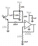
I'm trying to amplify a 1kHz square wave signal sent from a IR LED with a IR phototransistor and an Op-Amp (LM358).
I made up with this scheme but it doesn't work:

Capture.GIF

On point 1 I read a DC component plus the frequency which becomes bigger in amplitude as I approach the IR LED that transmits it.
On point 2 I only have the frequency.
It's all good for now. So I try to amplify this frequency by using tha Op Amp in Inverting Voltage Amplifing mode.
So Vout should be: ( -R2/R1 ) x Vin.
But it just doesn't work. The Vout is just too little, even less than Vin.
The all circuit is powered with 15V (not dual).
What am I doing wrong?
 

Tricka90, as your desired operating point is at Vcc/2 you must connect the positive opamp input to a Vcc/2 (voltage division using two equal resistors connected to Vcc).
 

Since your signal is square wave, you can also use opamp as a comparator (so that amplitude will swing between gnd to vcc).
Then you can add an resistor divider at the output of the opamp to adjust amplitude to desired value.
 

Thank you. I've tried connecting the plus terminal to a Vcc/2 DC voltage with a resistor voltage divider but still no good result.
Maybe I'm doing all wrong from the beginning.
Can I please ask you what is the best way to achieve what I'm trying to do?
I just want to amplify the IR frequency with the phototransistor and the Op Amp and get the amplified frequency on Out, which becomes bigger or smaller in amplitude when I approach or distance the IR transmitter LED.
 

I agree that the (+) input of the opamp must be properly biased at about half the supply voltage. Your existing unbiased opamp is a rectifier.

Your opamp is inverting with an input impedance of only 100 ohms that loads down the high impedance output of the photo-transistor. The gain of the opamp IS NOT -R2/R1 but is actually -R2/(R1 + the source impedance). Then the gain is fairly low.
Make the opamp non-inverting then it will have a high input impedance so that the photo-transistor is not loaded down.
 

Yes - Audioguru is right.
However, in non-inverting configuration the input resistance is determined by the voltage divider which - also in this case - is necessary.
More than that the feedback circuit must be connected to ground via another large capacitor (for a dc gain of unity).

Remark: My answer above is based on the assumption that you
* need an input couplig capacitor, and
* are using a single supply voltage.
 
Last edited:

You probably want a voltage gain at 1kHz of 1000 but the lousy old LM358 cannot do it. Its datasheet has a graph that shows a typical gain of about 400 because it rolls off high frequencies. Its output will not be a square-wave that has harmonics above 10kHz, instead it will be sort of like a sinewave and triangle wave combined.

Most audio opamps have a much higher frequency response but also do not have a gain of 1000 at 10kHz or more.
If your supply is a total of 7V or more then try a TL071 or TL081 single opamp or a TL072 or TL082 dual opamp to see if the squarewave is square enough.

Here is the schematic:
 

Attachments

  • amplifier for photo-transistor.png
    amplifier for photo-transistor.png
    11.7 KB · Views: 277
You probably want a voltage gain at 1kHz of 1000 but the lousy old LM358 cannot do it. Its datasheet has a graph that shows a typical gain of about 400 because it rolls off high frequencies. Its output will not be a square-wave that has harmonics above 10kHz, instead it will be sort of like a sinewave and triangle wave combined.

Most audio opamps have a much higher frequency response but also do not have a gain of 1000 at 10kHz or more.
If your supply is a total of 7V or more then try a TL071 or TL081 single opamp or a TL072 or TL082 dual opamp to see if the squarewave is square enough.

Here is the schematic:

AWESOME, it works Very Good thank you a lot! :-D
I'm using a TL081CN, and instead of the 100kohm resistor between inverting terminal and output I'm using an 1Mohm one to get even more gain, and all works fine!
There is only a little last problem. I found that the amplitude of the frequency on output varies a lot with ambient light.
After some tests I found that this problem is caused by the polarization of the phototransistor.
When the ambient is well lighted all works fine, but when the ambient is dark the phototransistor can't get enough polarization from ambient light so when the IR LED transmitter is far it cannot output enough collector current. If I use a photodiode instead of the phototransistor the problem disappears (but of course the output frequency is too low in amplitude). Do you think there is any way to solve this problem?
Thank you again for all your precious help.

- - - Updated - - -

I found there is also a more serious problem. When there is some light from lamps in the room, which lights at 100Hz (I live in Europe), the op amp amplifies also this wave. Is there any way to filter this out?
 

I think the term "polarization" isn't right, I would simply talk about DC current. But both photo transistor current gain and upper cut-off frequency will strongly depend on collector current. In so far, a photodiode would be a better solution. If the photo transistor has a base terminal, you can also apply artificial DC bias. Or use a bias light source.
 
Thank you FvM. The phototransistor I'm using doesn't have base terminal but I can buy one which does have it.
But what about the more critical problem:
I found there is also a more serious problem. When there is some light from lamps in the room, which lights at 100Hz (I live in Europe), the op amp amplifies also this wave. Is there any way to filter this out?
Can you think about a solution? With this problem I just can't use the circuit.
 

Use a photo-transistor that has a black coating that blocks ambient light but passes IR radiation.
If it still picks up 100Hz from electric lights then make a highpass filter that blocks low frequencies but passes high frequencies or make a notch filter (but the harmonics of 100Hz extend to higher frequencies. Use compact fluorescent light bulbs that operate at about 40kHz.
 
Thank you, I will try it.
Could you please tell me what is the function of the three 100kohm R and the 1uF C connected to the non-inverting input?
I can say that two R are used as a voltage divider to give the non-inverting input a Vcc/2 voltage, but I can't say what the last 100k resistor and the 1uF C should do. Is it some kind of filter?
The voltage divider biases the input of the opamp at half the supply voltage but the noise on the supply voltage is still there (reduced in level a little). The 1uF capacitor filters out high frequency noise from the power supply and prevents oscillation of the opamp.
The third 100k resistor is the input resistor for the opamp since if the input pin3 of the opamp is directly connected to the voltage divider then the 1uF capacitor will kill all input signals.
 
Perfect, thanks a lot! :D
And can I ask you why there is the 10uF C between 100 ohm R and ground? In the classic amplifier scheme the 100ohm R is connected directly to ground, with no capacitor!
 

Perfect, thanks a lot! :D
And can I ask you why there is the 10uF C between 100 ohm R and ground? In the classic amplifier scheme the 100ohm R is connected directly to ground, with no capacitor!

It`s for the correct bias point.
At the non-inv. input you have biased with Vcc/2. This potential must be transferred to the output. Thus you need a dc gain of unity only, see my answer in ppost#6.
(For all frequencies that can pass the capacitor you have the desired ac gain.
 

Status
Not open for further replies.

Similar threads

Part and Inventory Search

Welcome to EDABoard.com

Sponsor

Back
Top