Continue to Site

Welcome to EDAboard.com

Welcome to our site! EDAboard.com is an international Electronics Discussion Forum focused on EDA software, circuits, schematics, books, theory, papers, asic, pld, 8051, DSP, Network, RF, Analog Design, PCB, Service Manuals... and a whole lot more! To participate you need to register. Registration is free. Click here to register now.

Why no free wheel diode on FET in this circuit?

Status
Not open for further replies.

boylesg

Advanced Member level 4
Joined
Jul 15, 2012
Messages
1,023
Helped
5
Reputation
10
Reaction score
6
Trophy points
1,318
Location
Epping, Victoria, Australia
Activity points
11,697
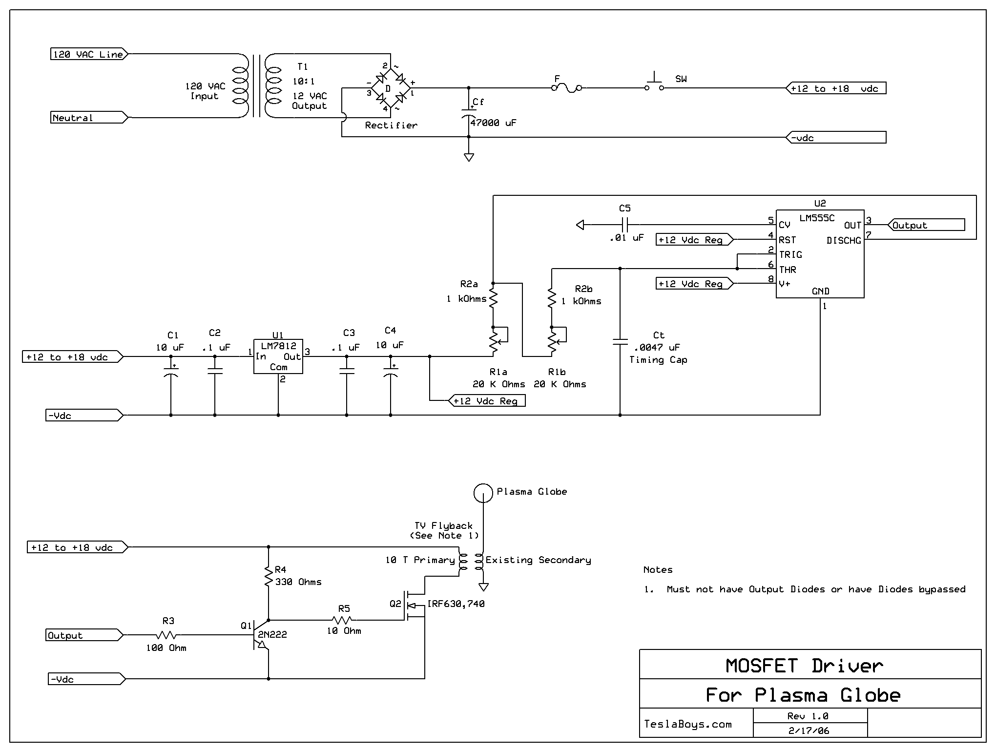
Can anyone explain why the designer has not used a free wheel diode on the FET in this circuit?


Even if the FET could withstand the reverse voltage why wouldn't you use a free wheel diode so that the current can flow in both directions through the coil and maximize power?
MOSFETDriver.gif
 

Apparently the designer WANTS a big voltage spike on the primary (and thus, also on the secondary). That's why there's the comment about no output diodes.
 

Apparently the designer WANTS a big voltage spike on the primary (and thus, also on the secondary). That's why there's the comment about no output diodes.

As I understand it, the designer is referring to the output diodes on a tv flyback transformer that he is using as the transformer in the schematic. They have output diodes on the HV secondary and these need to be removed or by passed, which involves grinding away the potting epoxy to expose them.
 

Well then, I guess he's just not worried about the inductive spike. Or he made a mistake.
 

Status
Not open for further replies.

Part and Inventory Search

Welcome to EDABoard.com

Sponsor

Back
Top